
Positive crankcase ventilation ("PCV") valve mounting structure

a technology for ventilation valves and crankcases, which is applied in the direction of crankcase ventillation, combustion engines, machines/engines, etc., can solve the problems of mounting structure, manufacturing and/or maintenance costs, and increase the cost of manufacturing and/or maintenance, and achieve the effect of convenient assembly and/or

Active Publication Date: 2016-05-05
AISAN IND CO LTD
View PDF6 Cites 7 Cited by
  • Summary
  • Abstract
  • Description
  • Claims
  • Application Information

AI Technical Summary

Benefits of technology

The invention is about a mounting structure for a PCV valve and a cylinder head in an engine. A gasket is used to seal the components together, reducing the number of parts and lowering manufacturing costs. A receiving-side stepped portion and an insertion-side stepped portion are formed on the joint surfaces of the cylinder head and intake manifold, and the gasket is easily positioned between them. The gasket also extends into both the cylinder head and intake manifold for a simultaneous seal between the valve case and both components.

Problems solved by technology

Thus, such an arrangement as described above may lead to an increase in costs associated with manufacturing and / or maintaining, for example, the mounting structure.

Method used


Image

  • Positive crankcase ventilation ("PCV") valve mounting structure
  • Positive crankcase ventilation ("PCV") valve mounting structure
  • Positive crankcase ventilation ("PCV") valve mounting structure

Examples


Embodiment Construction

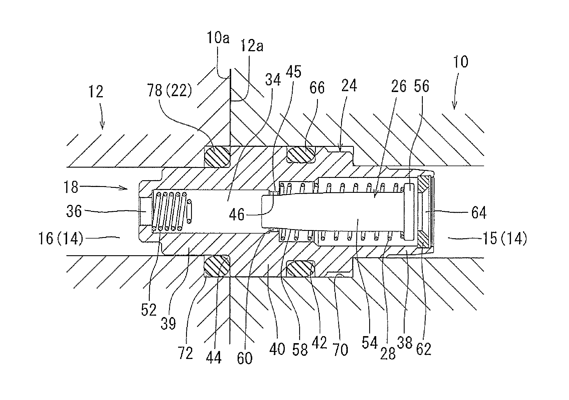
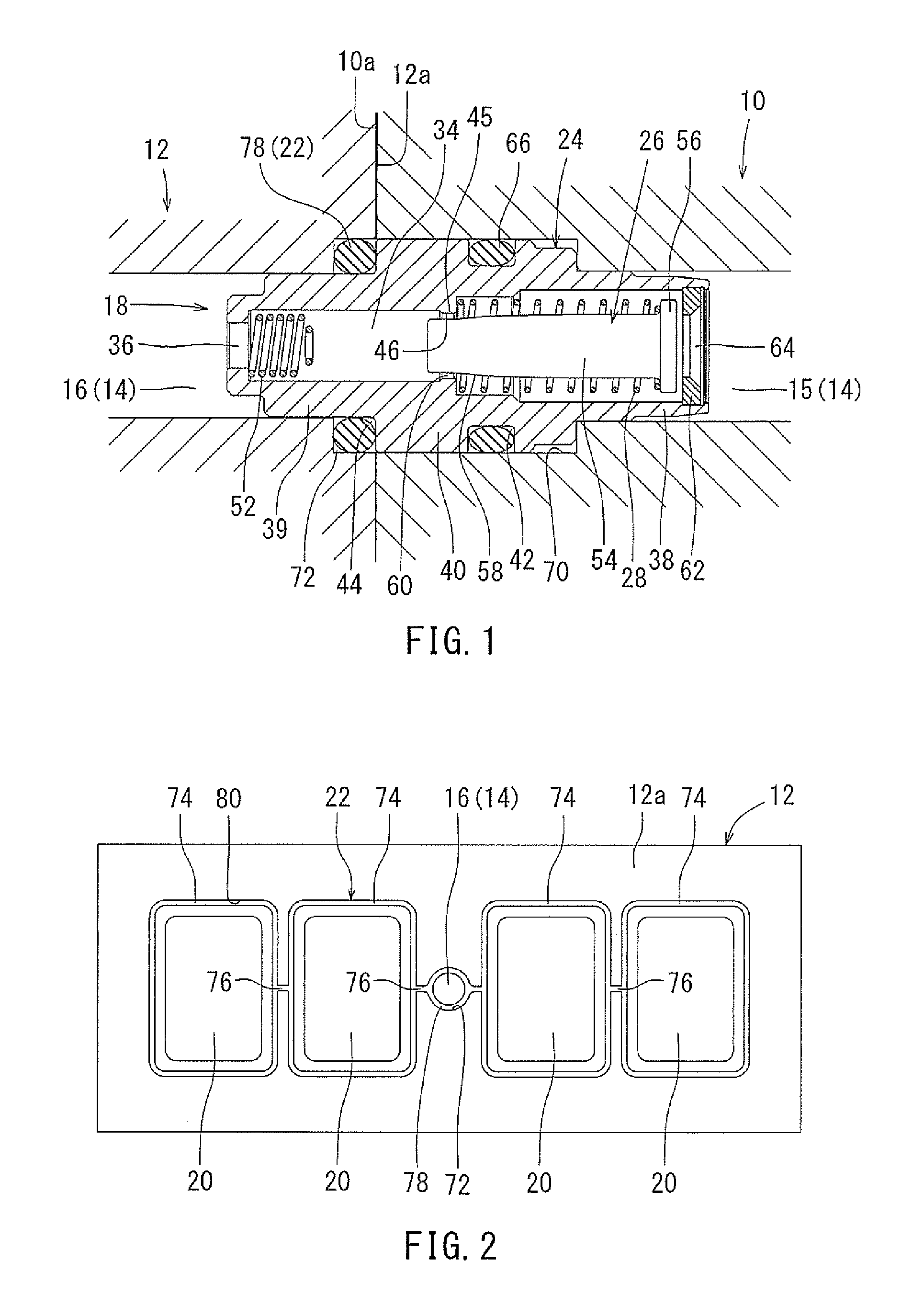
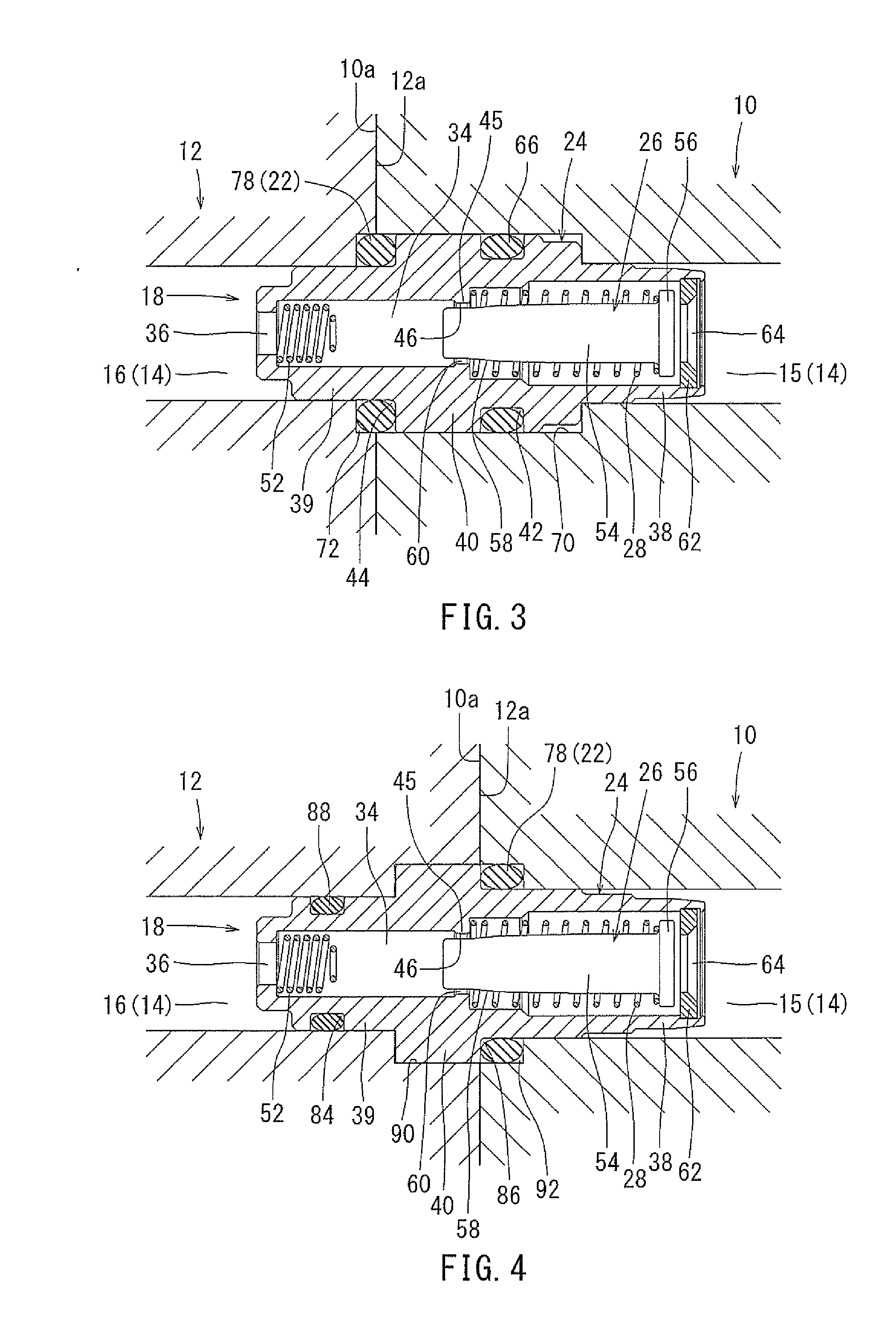
[0022]A PCV valve mounting structure, in accordance with a first embodiment, will now be described with reference to FIGS. 1 and 2. Referring to FIG. 1, a blow-by gas passage 14 may have an upstream-side passage portion 15 positioned upstream from a down-stream side passage portion 16, with respect to a direction of flow of blow by gas through the blow-by gas passage 14. The upstream-side passage portion 15 may be formed in a cylinder head 10 of an engine. In detail, the downstream-side end of the upstream-side passage portion 15 may open at a joint surface 10a of the cylinder head 10. The upstream-side end of the upstream-side passage portion 15 may be in fluid communication with a gas mixing and / or transference chamber (not shown in FIGS.) into which the blow-by gas may flow from combustion chambers of the engine. The mixing chamber, as described here, may be a “crank” chamber located in, for example, a crankcase of the engine or may be a separation chamber of an oil separator cou...


PUM


Abstract

A positive crankcase ventilation (PCV) valve mounting structure has a blow-by gas passage with an upstream-side passage portion and a down-stream-side passage portion positioned in a cylinder head and an intake manifold, respectively. The blow-by gas passage may receive the PCV valve therein such that an upstream side portion of a valve case of the PCV valve is positioned within the upstream-side passage portion and that a downstream side portion of the valve case is positioned within the down-stream-side passage portion when the cylinder head and the intake manifold are joined together. A gasket may seal the cylinder head to the intake manifold and may include a seal portion positioned between the valve case of the PCV valve and at lest one of the cylinder head and the intake manifold.

Description

CROSS-REFERENCE TO RELATED APPLICATIONS[0001]This application is based upon and claims priority to Japanese Patent Application Serial No. 2014-224163 filed on Nov. 4, 2014, the contents of which are incorporated herein by reference in their entirety for all purposes.STATEMENT REGARDING FEDERALLY SPONSORED RESEARCH OR DEVELOPMENT[0002]Not applicable.BACKGROUND[0003]The invention generally relates to a structure for mounting a positive crankcase ventilation valve (herein referred to as a “PCV” valve) to a cylinder head of an internal combustion engine, such as an engine for powering an automobile and / or any other vehicle engine. Further, the PCV valve may be mounted directly to an intake manifold of such an engine. Also, the PCV valve may direct and / or adjust flow of gas that may be recirculated from the engine and / or exhaust system of a vehicle, for example, back to the engine to enhance engine power delivery and efficiency.[0004]FIG. 6 illustrates a known PCV valve mounting structur...

Claims


Application Information

Patent Timeline
Patent Type & Authority Applications(United States)
IPC IPC(8): F01M13/00
CPCF01M2013/0038F01M13/0011
Inventor YAMADA, SHIGEKIKIDA, MASAHIRO
Owner AISAN IND CO LTD
Learn More