Control device for internal combustion engine with turbocharger

a control device and turbocharger technology, which is applied in the direction of electric control, ignition automatic control, machines/engines, etc., can solve the problems of deteriorating drivability, deteriorating emissions, and retardation of ignition timing, so as to improve the supercharging effect, and improve the effect of supercharging

Active Publication Date: 2016-05-05
TOYOTA JIDOSHA KK
View PDF5 Cites 11 Cited by
  • Summary
  • Abstract
  • Description
  • Claims
  • Application Information

AI Technical Summary

Benefits of technology

[0018]According to the above described functions, although on one hand the virtual air fuel ratio that is used to calculate the target air amount is switched from the first air-fuel ratio to the second air-fuel ratio, on the other hand the target air-fuel ratio is maintained at the first air-fuel ratio. As a result, the torque that can be achieved with the target air amount and the target air-fuel ratio is in excess of the requested torque, and retardation of the ignition timing is performed to compensate for the excessive amount of torque. Further, the target air-fuel ratio is maintained at the first air-fuel ratio until the ignition timing reaches the retardation limit. That is, the control device according to the present invention retards the ignition timing as far as the retardation limit. By this means, the energy of exhaust gas increases and a supercharging effect produces by the turbocharger increases, and it is possible to rapidly increase the air amount to the target air amount. Further, by not switching the target air-fuel ratio directly to the second air-fuel ratio, and instead temporarily switching the target air-fuel ratio to the third air-fuel ratio that is an intermediate air-fuel ratio that is richer than the second air-fuel ratio, the occurrence of a shortage in the actual torque relative to the requested torque can be avoided. Thereafter, although switching of the target air-fuel ratio to the second air-fuel ratio is performed at a time point at which a difference between the target air amount and the estimated air amount has become equal to or less than a threshold value, the time period until the estimated air amount converges on the target air amount is shortened by an improvement in the supercharging effect that is achieved by retarding the ignition timing as far as the retardation limit. Consequently, the time period from a time point at which the virtual air-fuel ratio is switched to the second air-fuel ratio until a time point at which the target air-fuel ratio is switched to the second air-fuel ratio is also shortened. That is, according to the control device of the present invention, in a case where a condition for switching from the first air-fuel ratio to the second air-fuel ratio that is leaner than the first air-fuel ratio is satisfied, the air-fuel ratio can be switched with favorable responsiveness without generating fluctuations in the torque.
[0019]Note that, in a non-supercharging region in which the turbocharger does not operate effectively, there is no necessity to retard the ignition timing as far as the retardation limit when switching the air-fuel ratio. In this case, from the viewpoint of fuel consumption performance, it is preferable to switch the target air-fuel ratio to the third air-fuel ratio as quickly as possible. Specifically, after changing of the virtual air-fuel ratio from the first air-fuel ratio to the second air-fuel ratio, the control device waits until an air amount that is estimated based on the operation amount of the first actuator reaches an air amount with which the requested torque can be achieved under the third air-fuel ratio. Subsequently, if the target intake pipe pressure has arrived at the supercharging region at the time point at which the estimated air amount reaches the aforementioned air amount, as described above, after waiting for the ignition timing to reach the retardation limit, the target air-fuel ratio is switched from the first air-fuel ratio to the third air-fuel ratio. However, if a target intake pipe pressure that is calculated based on the target air amount has not arrived at the supercharging region, the target air-fuel ratio is promptly switched from the first air-fuel ratio to the third air-fuel ratio, even if the relevant time point is prior to a time point at which the ignition timing reaches the retardation limit. Thus, the air-fuel ratio can be switched with favorable responsiveness without deteriorating the fuel consumption performance in the non-supercharging region.

Problems solved by technology

However, according to the aforementioned known method, although a torque level difference is lessened, there is the problem that the desired torque cannot be obtained, and because an air-fuel ratio that is not originally intended is used, there is a deterioration in the emissions.
However, retardation of the ignition timing is accompanied by the possibility of misfiring.
Misfiring leads to a deterioration in the drivability and a deterioration in exhaust performance.
Although misfiring can be prevented by setting restrictions for retardation of the ignition timing, if retardation of the ignition timing is simply restricted, an increase in torque that is caused by an excessive fuel amount cannot be avoided.
Consequently, in a case where retardation of the ignition timing is simply restricted, it takes time for the air amount to reach the target air amount due to the influence of turbo lag, and there is a concern that it will not be possible to promptly switch the air-fuel ratio.

Method used


Image

  • Control device for internal combustion engine with turbocharger
  • Control device for internal combustion engine with turbocharger
  • Control device for internal combustion engine with turbocharger

Examples


embodiment 1

[0027]Hereunder, Embodiment 1 of the present invention is described with reference to the drawings.

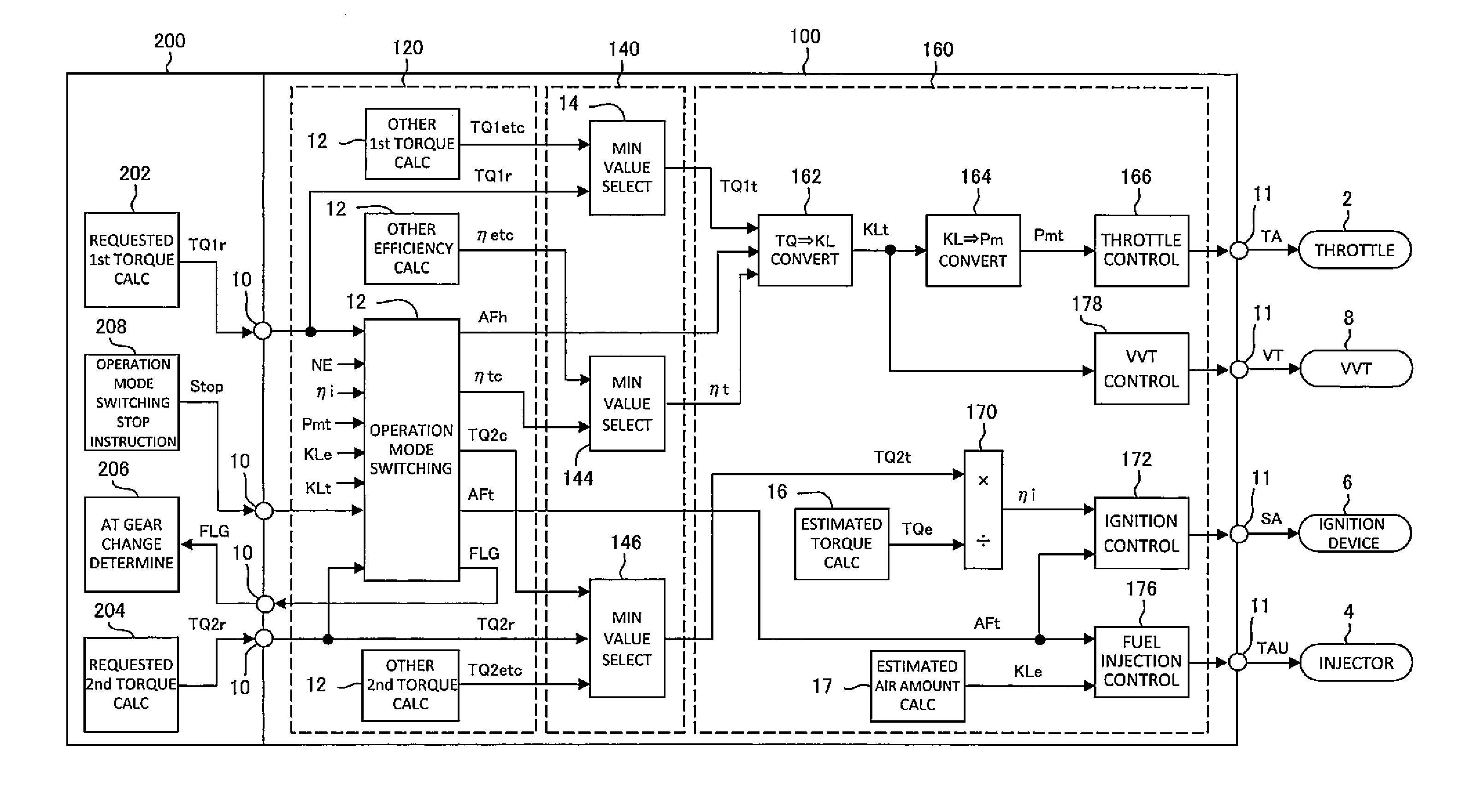
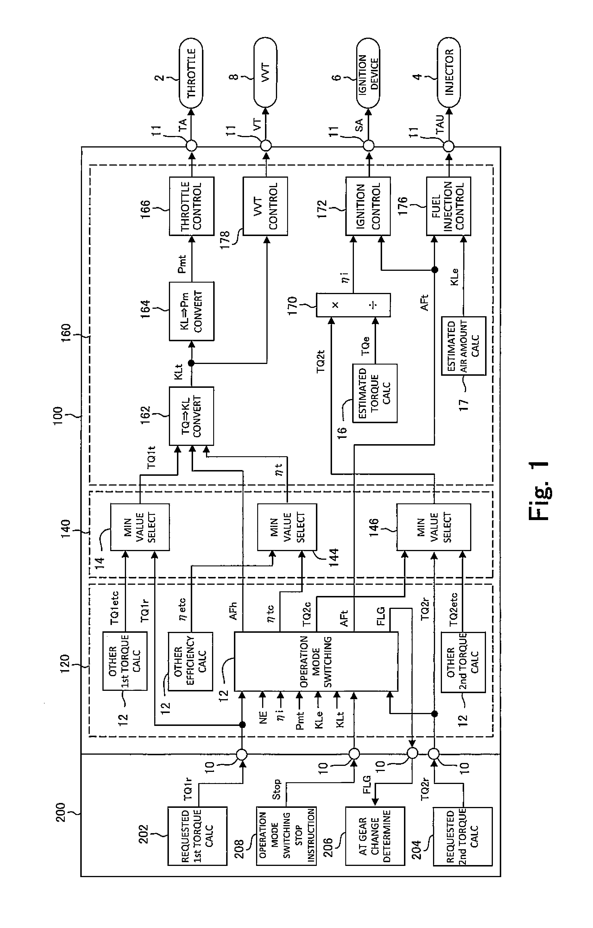
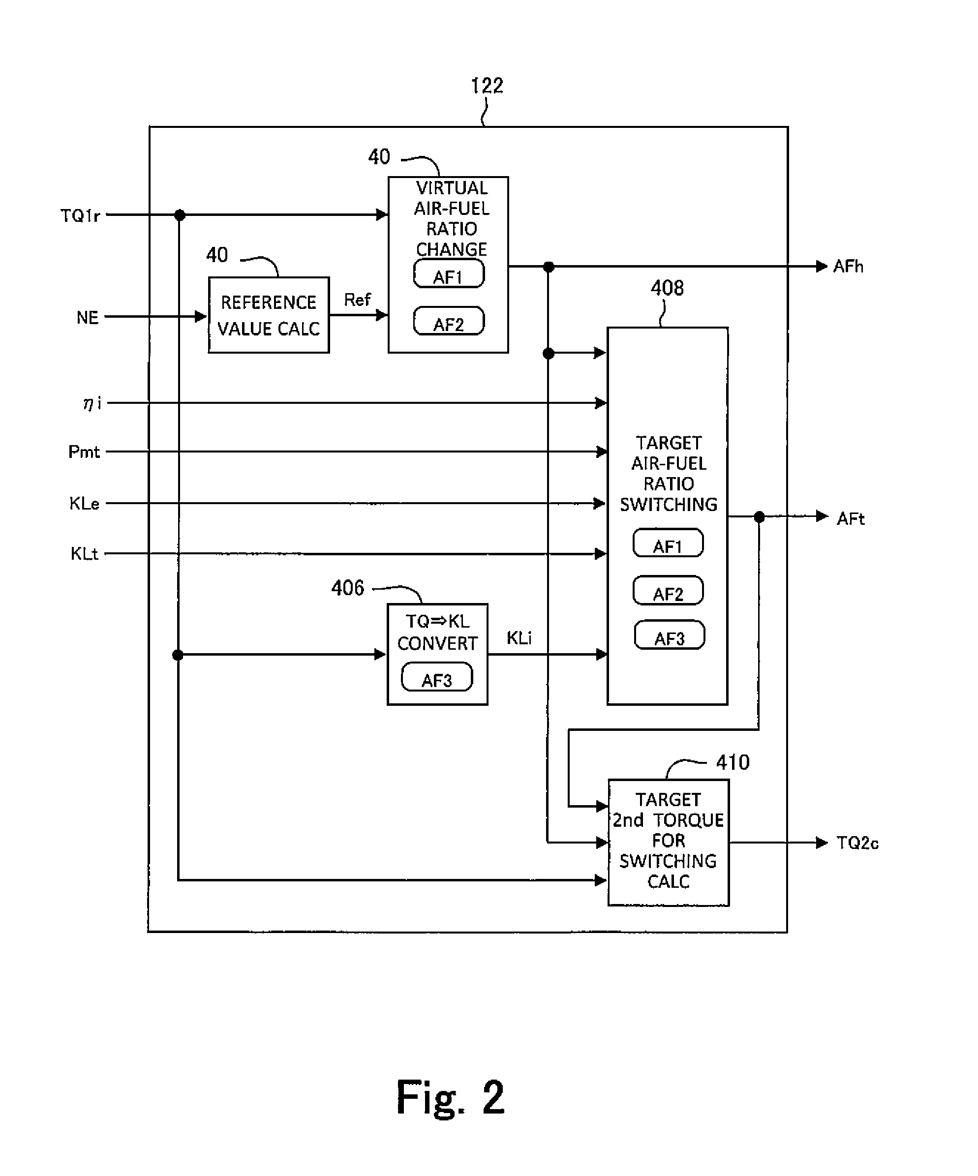
[0028]An internal combustion engine (hereinafter, referred to as “engine”) which is a control object in the present embodiment is a spark-ignition type, four-cycle reciprocating engine, and is a turbo engine in which a turbocharger is installed. Further, the engine is a so-called “lean-burn engine” that is configured to be capable of selecting between a stoichiometric mode (first operation mode) that performs operation according to a theoretical air-fuel ratio and a lean mode (second operation mode) that performs operation according to an air-fuel ratio that is leaner than the theoretical air-fuel ratio as the operation mode of the engine.

[0029]An ECU (electrical control unit) mounted in the vehicle controls operations of the engine by actuating various kinds of actuators that are provided in the engine. The actuators actuated by the ECU include a throttle and a variable valve timing d...

embodiment 2

[0100]Next, Embodiment 2 of the present invention will be described with reference to the drawing.

[0101]An engine that is taken as a control object according to the present embodiment is a lean-burn engine with a turbocharger, similarly to Embodiment 1. Actuators that are actuated by an ECU that controls the operations of the engine according to the present embodiment include, in addition to a throttle, a VVT, an ignition device and an injector, a waste gate valve (hereunder, referred to as “WGV”) that is provided in a turbocharger. The WGV is a supercharging characteristic varying actuator that varies a supercharging characteristic of the turbocharger. Because a supercharging characteristic of the turbocharger causes an air amount to change, the WGV is included in the first actuator that causes an air amount to change, similarly to the throttle and VVT.

[0102]In FIG. 7, the logic of the ECU according to the present embodiment is illustrated by means of a block diagram. The ECU inclu...


PUM


Abstract

A target air amount for achieving a requested torque is back-calculated from the requested torque using a virtual air-fuel ratio. The virtual air-fuel ratio is changed from a first air-fuel ratio to a second air-fuel ratio in response to a condition for switching an operation mode being satisfied. After the virtual air-fuel ratio is changed, the target air-fuel ratio is maintained at the first air-fuel ratio until the ignition timing reaches a retardation limit. Subsequently, in response to the ignition timing reaching the retardation limit, the target air-fuel ratio is switched from the first air-fuel ratio to a third air-fuel ratio. After switching of the target air-fuel ratio, in response to a difference between the target air amount and an estimated air amount becoming equal to or less than a threshold value, the target air-fuel ratio is switched from the third air-fuel ratio to the second air-fuel ratio.

Description

TECHNICAL FIELD[0001]The present invention relates to a control device that performs integrated control of an air amount, a fuel supply amount and an ignition timing of an internal combustion engine with a turbocharger that is configured to be capable of switching an air-fuel ratio that is used for operation between at least two target air-fuel ratios.BACKGROUND ART[0002]In JP11-22609A, technology (hereunder, referred to as “prior art”) is disclosed that relates to control for switching a combustion system in an internal combustion engine in which the combustion system of the internal combustion engine can be switched from stratified combustion to homogeneous combustion, or from homogeneous combustion to stratified combustion. Since an air-fuel ratio during stratified combustion is leaner than an air-fuel ratio during homogeneous combustion, switching of the air-fuel ratio accompanies switching of the combustion system. Known methods for switching an air-fuel ratio include a method ...

Claims


Application Information

Patent Timeline
Patent Type & Authority Applications(United States)
IPC IPC(8): F02D23/02F02P5/15F02D41/30F02D13/02F02D41/00
CPCF02D23/02F02D13/0234F02P5/15F02D41/3017F02D41/0007F02D23/00F02D41/3029F02D41/3064F02B37/18F02D11/105F02D2041/001F02D2200/1004F02P5/045F02P5/1502F02P5/1528F02D2200/0402Y02T10/12Y02T10/40
Inventor SAITO, YUSUKEADACHI, NORIYASUTANAKA, SATORUYOSHIZAKI, SATOSHIMORIGUCHI, RYUTAROMATSUMOTO, YOSUKE
Owner TOYOTA JIDOSHA KK
Why Eureka
Try Eureka