
Micromanipulator for a cryomicrotome

a micromanipulator and microtome technology, applied in the field of micromanipulators for cryomicrotomes, can solve the problems of preventing the source of errors in the context of manual handling, and achieve the effects of improving operation convenience, facilitating specimen handling, and more flexible handling

Active Publication Date: 2016-05-05
LEICA MICROSYSTEMS GMBH
View PDF4 Cites 1 Cited by
  • Summary
  • Abstract
  • Description
  • Claims
  • Application Information

AI Technical Summary

Benefits of technology

[0014]The micromanipulator according to the present invention enables substantially improved, precise positioning of the specimen holder during the operation of loading the specimen holder with the sections. A further advantage of an embodiment of the present invention described herein is that a grid loaded with sections can be laid into a transfer container without having to perform a removal of the retaining tool from the micromanipulator, by way of a positioning motion of the manipulator.
[0025]Lastly, the fact that one or more axes of motion of the micromanipulator are motorized can represent an additional improvement in operating convenience, in an embodiment of the present invention.

Problems solved by technology

In particular, sources of error in the context of manual handling are to be precluded.

Method used


Image

  • Micromanipulator for a cryomicrotome
  • Micromanipulator for a cryomicrotome
  • Micromanipulator for a cryomicrotome

Examples


Embodiment Construction

[0031]Reference will be made in detail to one or more embodiments of the present invention, one or more examples of which are illustrated in the accompanying drawings.

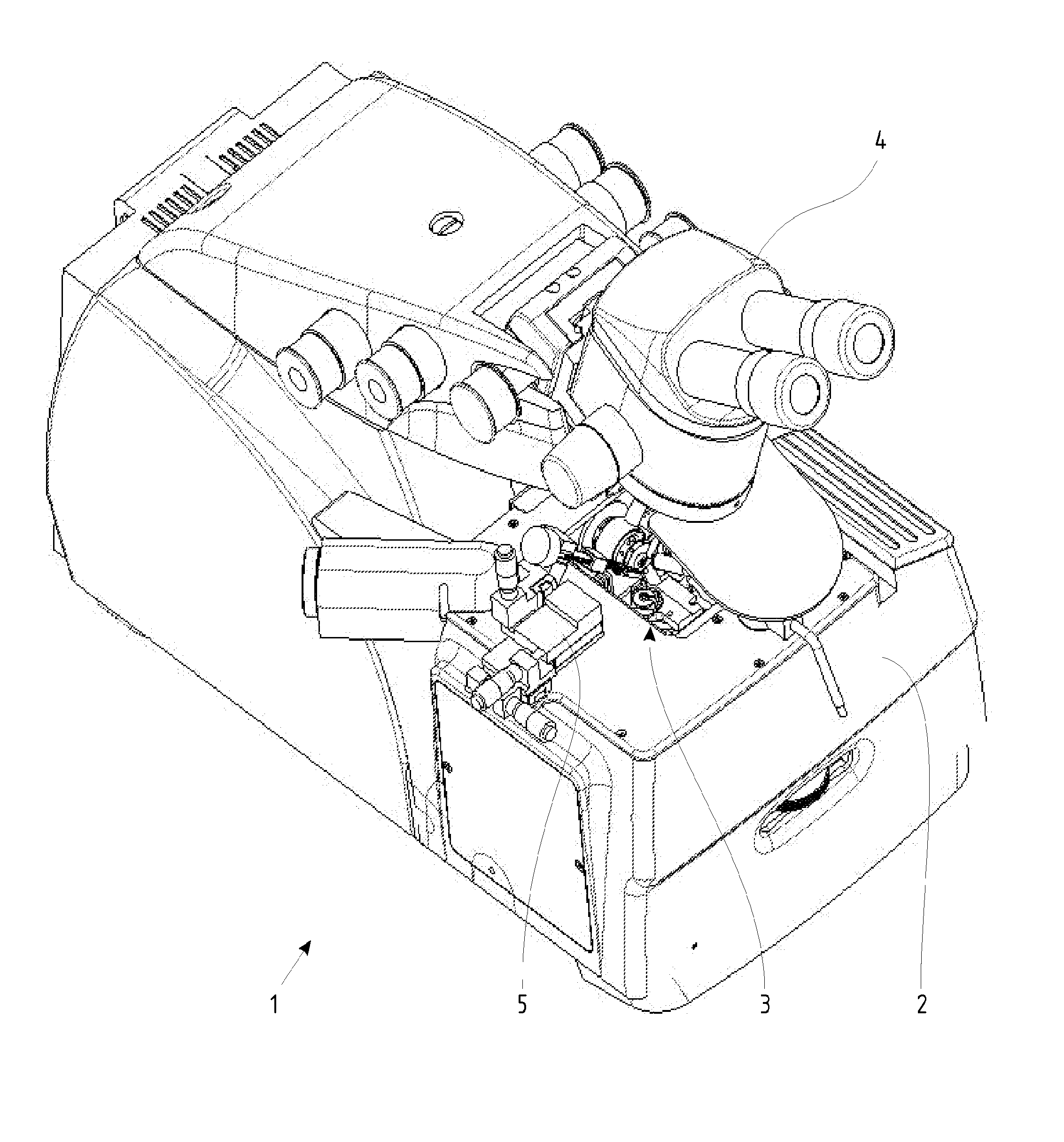
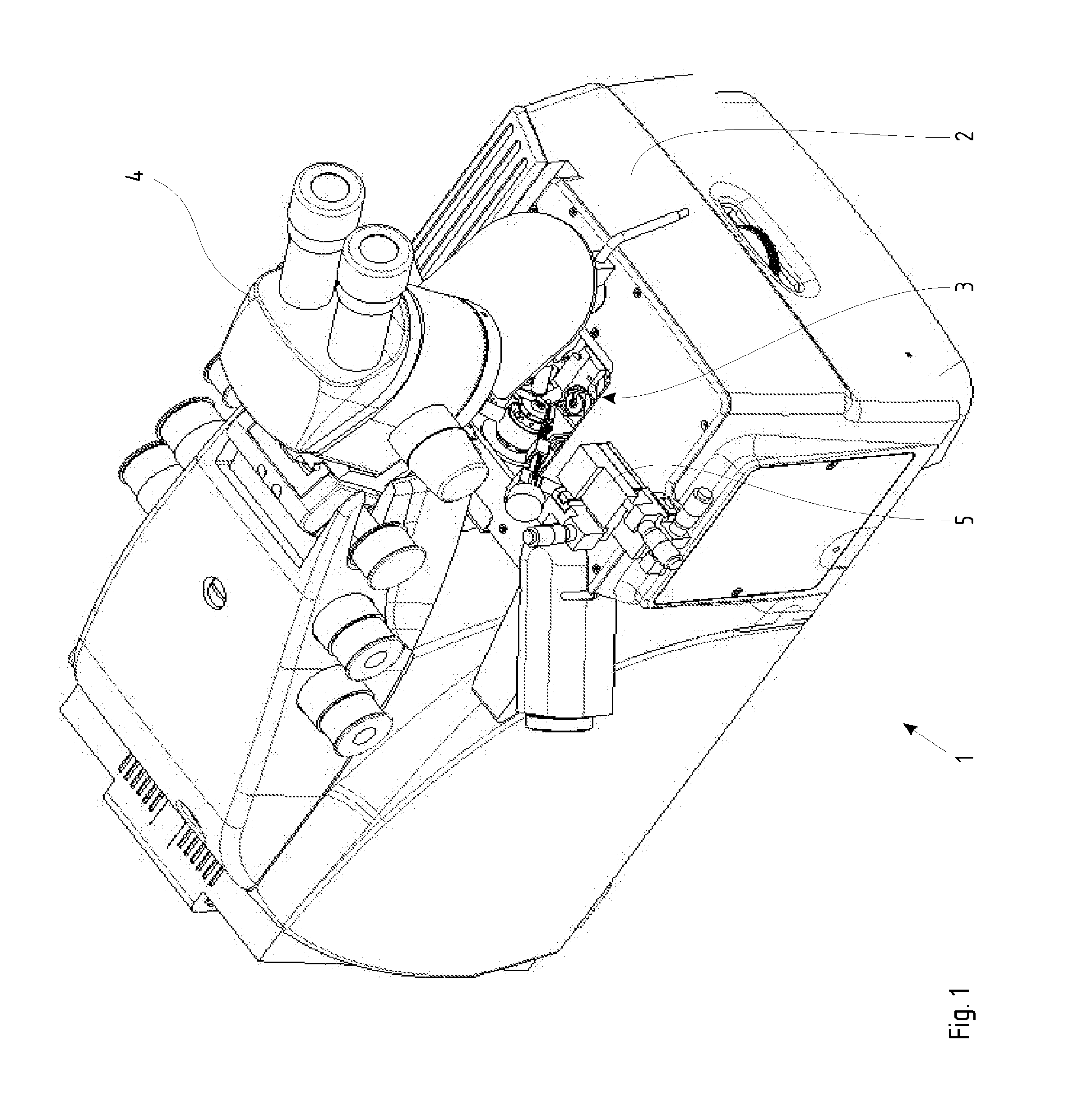
[0032]FIG. 1 shows an ultramicrotome 1 that is based on the above-described Leica EM FC6 and, in a manner known with regard to that device, comprises a cooling chamber 2 having a working chamber 3 surrounded by the cooling chamber, in which the tools for the production of sections are housed. A stereomicroscope 4 serves, in a manner also known, for observing the preparation and the sections during sectioning and subsequent manipulation. In a departure from known devices, a manipulator 5 is installed on one side of the cooling chamber. As a rule, manipulator 5 is located on the left side in order to enable manual manipulation of the specimens from the right side of the device, although installation on the right side is, of course, also possible (especially for left-handers).

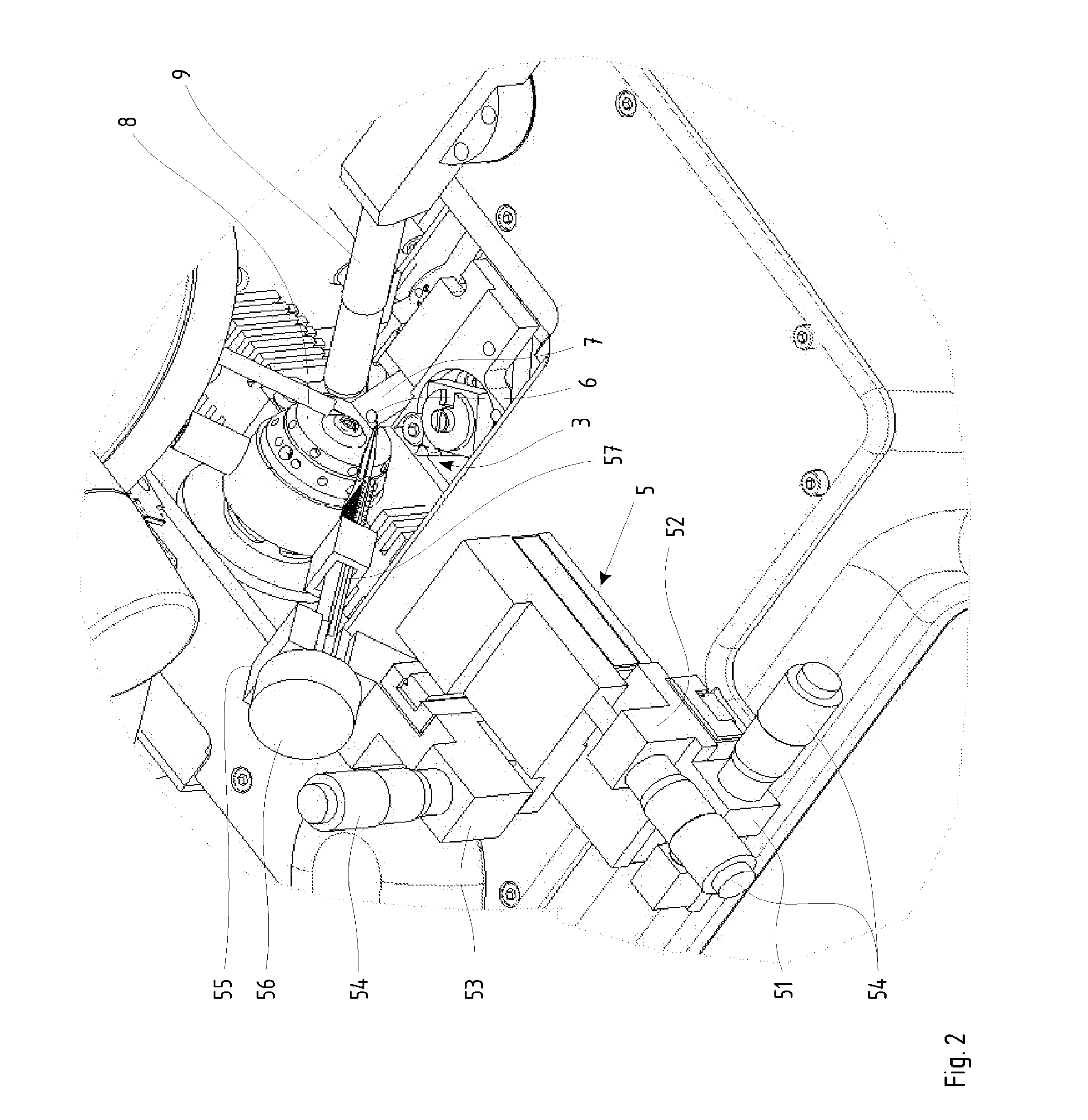
[0033]Manipulator 5 is shown in further detail...


PUM

PropertyMeasurementUnit
thicknessaaaaaaaaaa
angleaaaaaaaaaa
cryoelectron microscopyaaaaaaaaaa

Abstract

A microtome system has a cryomicrotome with a sectioning device in which is provided a preparation holder and a knife edge that are guided past one another inside a working space during a sectioning operation, in order to produce thin sections of a preparation retained in the preparation holder. A micromanipulator is operable outside the working space. With the micromanipulator, a tool for retention of a specimen support is positioned proximate the knife edge during a sectioning operation in order to receive the sections that are produced, preferably for substantially stationary retention of the specimen support.

Description

[0001]The present application is a division of U.S. application Ser. No. 12 / 337193, filed Dec. 17, 2008, which claims the benefit of Austrian Patent Application No. AT 75 / 2008, filed Jan. 18, 2008, the entire disclosure of each of which are hereby incorporated by reference herein.[0002]The invention relates to a microtome, in particular a cryomicrotome, having a sectioning device in which are provided a preparation holder and a knife edge that are guided past one another inside a working space during a sectioning operation, in order to produce thin sections of a preparation retained in the preparation holder.BACKGROUND[0003]The production of thin sections of cryopreserved specimens, in particular biological specimens with vitrified material (i.e. solidified in glassy fashion), is important for cryoelectron microscopy and similar investigation methods. Cryopreserved specimens largely avoid distortions that can derive from desiccation, chemical modifications (including contrast agents...

Claims


Application Information

Patent Timeline
Patent Type & Authority Applications(United States)
IPC IPC(8): G01N1/06G01N1/42
CPCG01N1/42G01N1/06Y10T83/222Y10T83/283Y10T83/6508Y10T83/6571B26D1/00B26D1/105B26D1/1575
Inventor LIHL, REINHARDZIMMERMANN, MICHAEL
Owner LEICA MICROSYSTEMS GMBH
Learn More