Virtual image display apparatus

a virtual image and display device technology, applied in the field of virtual image display devices, can solve the problems of image degradation, easy recognition, uncomfortable image observation attitude, etc., and achieve the effect of changing luminan

Inactive Publication Date: 2016-05-05
SEIKO EPSON CORP
View PDF21 Cites 128 Cited by
  • Summary
  • Abstract
  • Description
  • Claims
  • Application Information

AI Technical Summary

Benefits of technology

[0056]In contrast, since the color light has a wavelength width of 10 nm or wider, light rays classified into the same color but having different wavelengths are incident on the first light-incident-side diffraction grating, their optical paths in the first light guide can be made different from each other, whereby the positions where light rays that form the light classified into the color exits can be reliably dispersed, and the change in luminance described above can be reliably avoided.

Problems solved by technology

In the configuration of the transparent slab described above, however, part of the light is reflected off the interfaces described above and reaches the viewer's eyes, resulting in the following problems in an application in which the displayed image is viewed from arbitrary viewing positions: The presence of the transparent slab is likely to be recognized; and the presence of the interfaces and the gaps between the interfaces are superimposed on the displayed image and likely to be recognized as noise.
The difference in the luminance undesirably causes the presence of the interfaces and the gaps between the interfaces to be likely to be visually recognized and eventually results in degradation in an image viewed through the transparent slab.
In this case, however, the central light described above that exits out of the first light guide via the first light-exiting-side diffraction grating is undesirably inclined to the light exiting surface of the first light-exiting-side diffraction grating when the central light exits through the light exiting surface, and the central light does not therefore exit along a normal to the first light exiting surface described above.
When the central light described above does not travel along a normal to the first light exiting surface as described above, the viewer needs to incline the sight direction with respect to the first light exiting surface, resulting in an uncomfortable image observation attitude.

Method used


Image

  • Virtual image display apparatus
  • Virtual image display apparatus
  • Virtual image display apparatus

Examples


first embodiment

Variation of First Embodiment

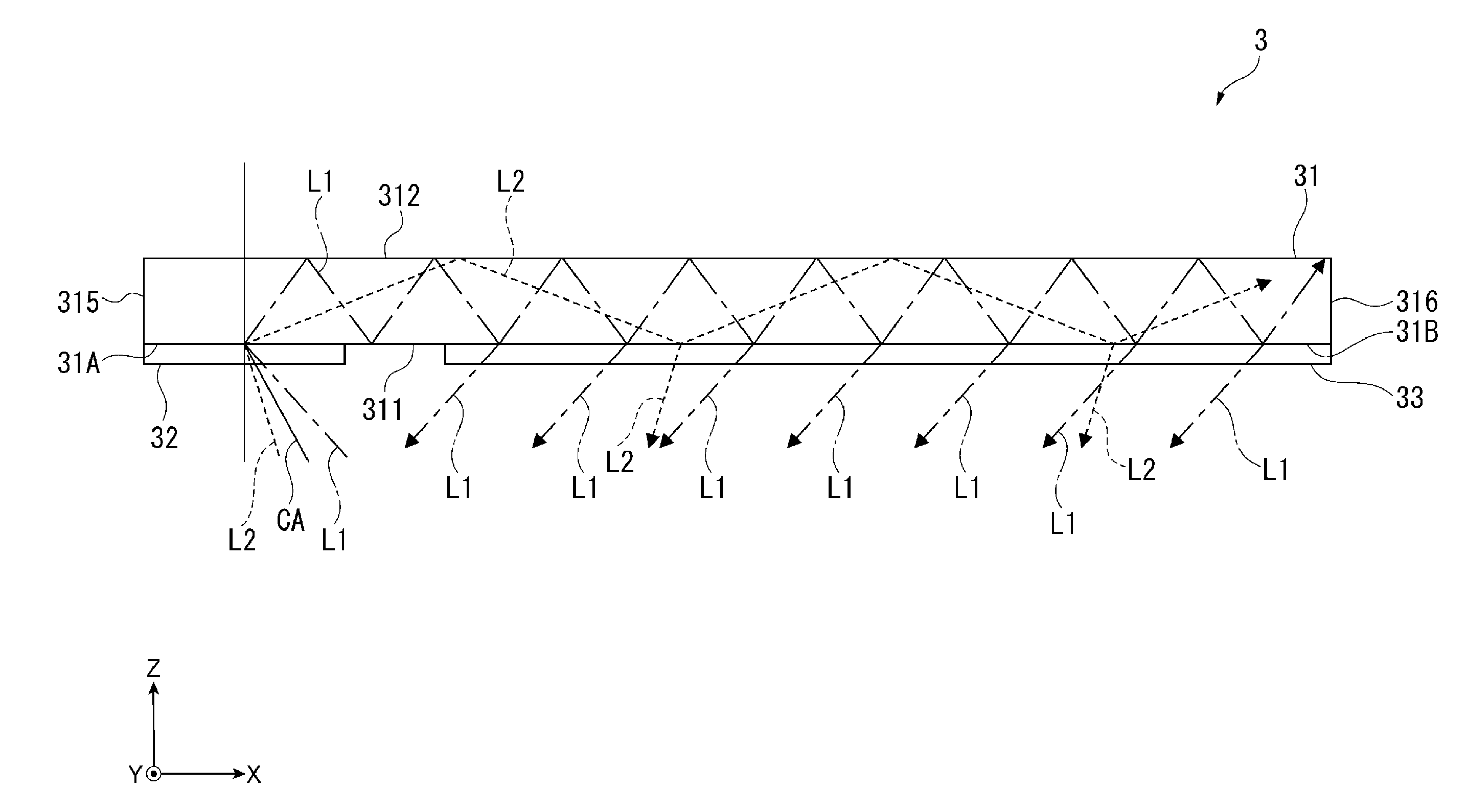
[0139]In the virtual image display apparatus 1 described above, since whenever the light rays repeatedly undergoing internal reflection and traveling reach the light exiting surfaces 31B and 41B, a predetermined proportion of the light rays exit to the outside and the remaining light rays undergo internal reflection, the amount (luminance) of light rays that exit through the light exiting surfaces 31B and 41B decreases (lowers) as the light rays travel in the light guides 31 and 41 in the light traveling direction. Specifically, the amount of light that exits out of the light-exiting-side diffraction grating 33 decreases with distance in the X direction, which is away from the light incident surface 31A, and the amount of light that exits out of the light-exiting-side diffraction grating 43 decreases with distance in the Y direction, which is away from the light incident surface 41A. As a result, the luminance of an image visually recognized not only on ...

second embodiment

[0152]A second embodiment of the invention will next be described.

[0153]A virtual image display apparatus according to the present embodiment has a direction adjustment layer as wells as the same configuration as that of the virtual image display apparatus 1 described above. The direction adjustment layer is disposed on the light exiting side of the light-exiting-side diffraction grating 43, which forms the light-exiting-side light guide apparatus 4, and adjusts the traveling direction of the light having exited out of the light-exiting-side diffraction grating 43. In this regard, the virtual image display apparatus according to the present embodiment differs from the virtual image display apparatus 1 described above. In the following description, portions that are the same or roughly the same as those having already been described have the same reference characters and will not be described.

[0154]FIG. 11 is a diagrammatic view showing the configuration of a virtual image display ap...

third embodiment

[0160]A third embodiment of the invention will next be described.

[0161]A virtual image display apparatus according to the present embodiment has a configuration similar to that of the virtual image display apparatus 1 described above. In the virtual image display apparatus 1, the projection apparatus 2 is located on the opposite side of the light-incident-side light guide apparatus 3 to the Z-direction side and projects the display light flux described above in the Z direction. In contrast, in the virtual image display apparatus according to the present embodiment, the projection apparatus is located on the Y-direction side of the light-incident-side light guide apparatus 3 and projects the display light flux described above in the direction opposite the Y direction. In this regard, the virtual image display apparatus according to the present embodiment differs from the virtual image display apparatus 1 described above. In the following description, portions that are the same or rou...


PUM


Abstract

A virtual image display apparatus includes a first light guide that not only causes a display light flux incident through a first light incident surface to repeatedly undergo internal reflection to travel in a first direction away from the first light incident surface but also causes part of the display light flux to exit to the outside through areas of a first light exiting surface that is at least one of interfaces with the outside and extends in the first direction, a first light-incident-side diffraction grating that diffracts light incident thereon to cause the diffracted light to enter the first light guide, and a first light-exiting-side diffraction grating that diffracts light incident from the first light guide.

Description

BACKGROUND[0001]1. Technical Field[0002]The present invention relates to a virtual image display apparatus.[0003]2. Related Art[0004]There is a known flat-panel projection display of related art that allows visual recognition of an image projected from a video projector in the form of a virtual image (see Japanese Patent No. 3,990,984, for example).[0005]The projection display described in Japanese Patent No. 3,990,984 includes a transparent rod and transparent slab, a video projector, and two mirrors.[0006]The transparent slab has a structure in which a plurality of float glass pieces layered on each other with glue having a selected refractive index are polished into a box-shaped slab and is so disposed that the interferences between the glue and the glass pieces are inclined to the horizontal direction by 45°. The transparent rod, which is formed in the same manner as the transparent slab described above, has a roughly rectangular cross section corresponding to the thickness dime...

Claims


Application Information

Patent Timeline
Patent Type & Authority Applications(United States)
IPC IPC(8): G02B27/01G02B27/00F21V8/00
CPCG02B27/0101G02B6/0023G02B2027/011G02B27/0037G02B6/005G02B6/34
Inventor SHINBO, AKIRAYOKOYAMA, OSAMUYONEKUBO, MASATOSHI
Owner SEIKO EPSON CORP
Why Eureka
Try Eureka