
Radio frequency anisotropic patch antenna and polarization selective surface

a radio frequency anisotropic patch and antenna technology, applied in the direction of antenna details, antennas, basic electric elements, etc., can solve the problems of rf antennas that cannot stand up to significant wear and tear, lack of polarization selectivity inherently built into the surface shape or material properties of standard conductive materials such as copper, and failure to meet significant wear and tear

Active Publication Date: 2016-05-05
US SEC THE ARMY THE
View PDF5 Cites 12 Cited by
  • Summary
  • Abstract
  • Description
  • Claims
  • Application Information

AI Technical Summary

Benefits of technology

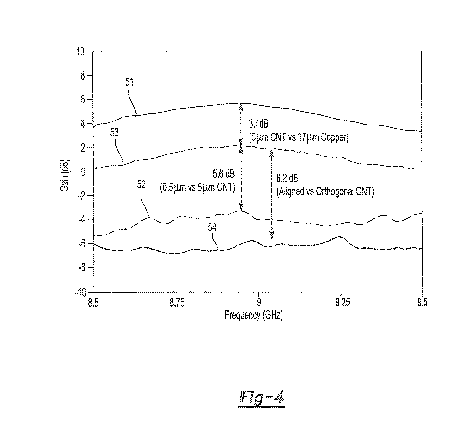
The present invention provides a radio frequency patch antenna that overcomes the limits of previous antennas. The antenna has a surface with an inherent anisotropic conductivity, which makes its aperture polarization selective based on the orientation of the nanomaterials that make up the patch. The orientation of the anisotropic material relative to the orientation of the feed line affects the resonance and efficiency of the patch antenna. A co-aligned feed line and patch can achieve the same efficiency as a non-anisotropic material. However, when the fibers or carbon nanotubes are aligned perpendicular to the feed line, the efficiency is significantly less, and the resonant frequency of the patch depends on the orientation of the feed line.

Problems solved by technology

This presents a variety of design challenges.
Antennas fabricated from standard conductive materials such as copper do not have polarization selectivity inherently built into their surface shape or material properties.
In addition, they fail to stand up to significant “wear and tear” due to the corrosion, limited flexibility, and lack of durability.
Such RF antennas are limited in their placement to areas on the platform such as a helmet, uniform, and equipment pack, that see minimal flexing and bending.

Method used


Image

  • Radio frequency anisotropic patch antenna and polarization selective surface
  • Radio frequency anisotropic patch antenna and polarization selective surface
  • Radio frequency anisotropic patch antenna and polarization selective surface

Examples


Embodiment Construction

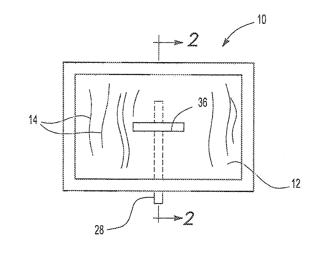
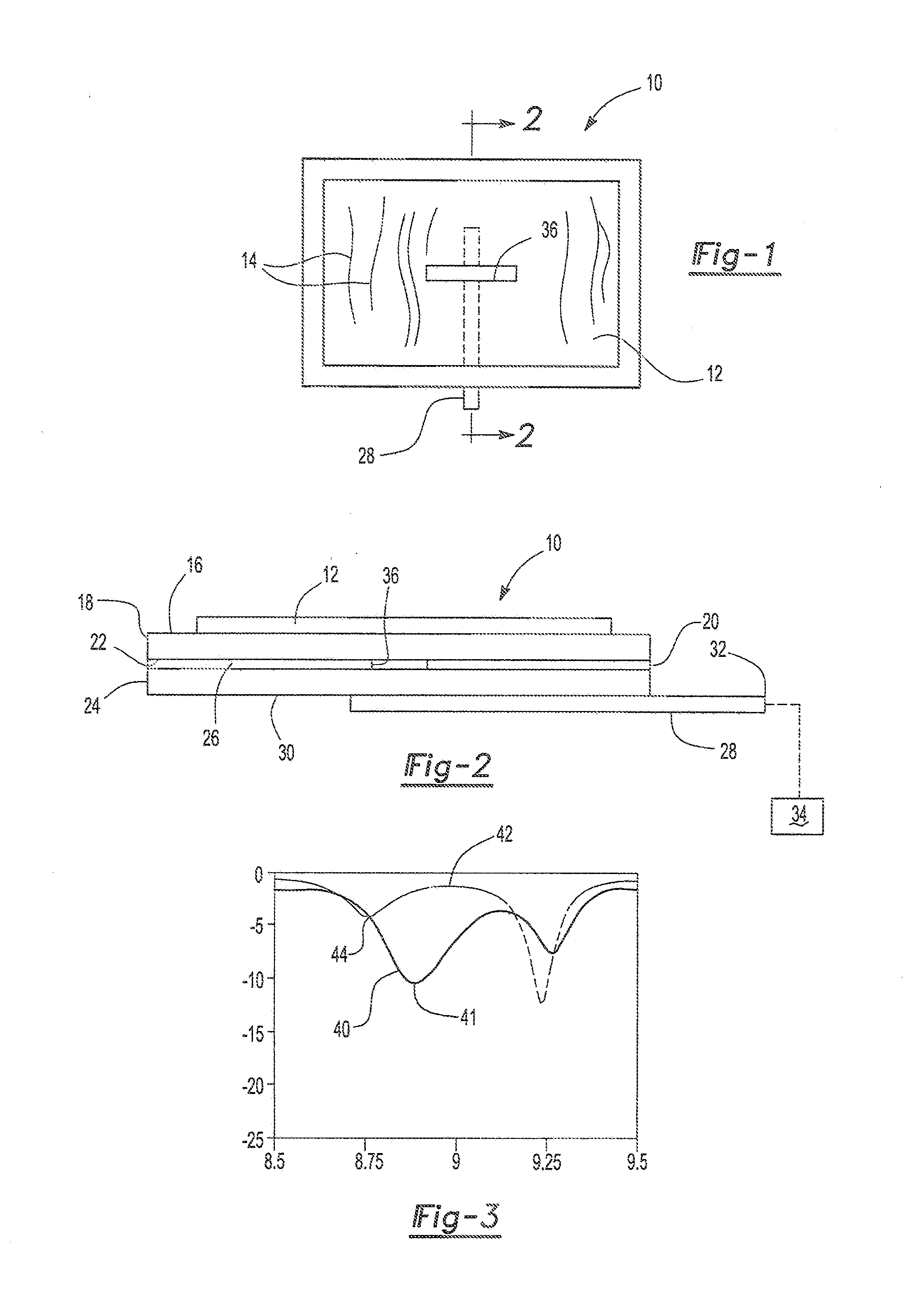
[0022]With reference first to FIGS. 1 and 2, an RF patch antenna 10 according to the present invention is illustrated. The patch antenna 10 typically operates at relatively high frequencies, such as the X band, although other frequencies may be used without deviation from the spirit or scope of the invention. Furthermore, in microwave RF antenna systems, such as the X band, a single antenna may be formed by a series of patch antennas 10. The use of a plurality of patches allows steering of the RF system using conventional techniques, such as phase shifting of the signal provided to the various patch antennae.

[0023]The patch antenna 10 includes an upper patch 12 constructed of an anisotropic material. Preferably, the anisotropic material comprises carbon nanotube sheet material. Such CNT sheet material includes carbon nanotubes 14 which are aligned in substantially the same direction. Preferably, the patch 12 has a thickness, typically between 0.5 micrometers and 5 micrometers and ca...


PUM


Abstract

A radio frequency patch antenna having a radiator patch constructed of an anisotropic material, such as carbon nanotube sheet material. Such material is flexible so that the antenna may be wearable and / or integrated into a textile substrate. A feed line couples the radio signal to the patch. Furthermore, the efficiency of radiation from the patch is directly related to the orientation of the fibers or carbon nanotubes in the anisotropic material relative to the orientation of the feed line. Dual polarized radiators can be constructed from two orthogonal layers of CNT patches fed with correspondingly orthogonal feed lines.

Description

CROSS REFERENCE TO RELATED APPLICATIONS[0001]This application depends from and claims priority to U.S. Provisional Application No. 62 / 074,110 filed Nov. 03, 2014, entitled, “Polarization Selective Nanomaterial Antennas,” the entire disclosure of which is incorporated herein by reference.GOVERNMENT INTEREST[0002]The invention described herein may be manufactured, used, and licensed by or for the United States Government.BACKGROUND OF THE INVENTION[0003]1. Field of the Invention[0004]The present invention relates generally to radio frequency antennas and polarization selective surfaces, more particularly, to a radio frequency patch antenna and surface with anisotropic features constructed, for example, using carbon nanotubes (CNT).[0005]2. Description of Related Art[0006]Solid surface patch antennas derive their polarization status from their feeding mechanism. Both patches and feed lines can be printed on a flexible surface and can be integrated into body worn radio frequency (RF) sy...

Claims


Application Information

Patent Timeline
Patent Type & Authority Applications(United States)
IPC IPC(8): H01Q9/04H01Q15/24
CPCH01Q9/0407H01Q9/045B82Y10/00Y10S977/742Y10S977/95H01Q15/24H01Q9/0457H01Q1/364
Inventor KELLER, STEVEN D.ZAGHLOUL, AMIR I.
Owner US SEC THE ARMY THE
Learn More