Micro camera and multi-purpose mounting base

a multi-purpose, mounting base technology, applied in the direction of coupling device connection, magnetic body, television system, etc., can solve the problems of restricting the possible orientation, unable to adjust the angle on which a device is mounted, and the rotatable socket only allows one freedom along the rotational axis, etc., to achieve convenient mounting and repositioning

Active Publication Date: 2016-05-05
UBIQUITI INC
View PDF9 Cites 59 Cited by
  • Summary
  • Abstract
  • Description
  • Claims
  • Application Information

AI Technical Summary

Benefits of technology

[0013]One embodiment provides a power connector that facilitates mounting and repositioning an electronic device. The power connector can include a curved receptacle surface comprising a surface that forms a semi-sphere and can mate with a curved contact surface of an electronic device. The power connector and / or the electronic device can include a device-coupling mechanism that can maintain the curved contact surface of the electronic device pressed against the curved receptacle surface of the power connector device, while an angle of the electronic device changes with respect to the power connector. The power connector and / or the electronic device can also include a power-transfer mechanism that can transfer at least power from the power connector to the electronic device, without an electrical wire between the power connector and the electronic device, while the angle of the electronic device changes with respect to the power connector.
[0018]In some embodiments, the power connector can include a magnet that emits a first magnetic field that attracts the electronic device to the receptacle surface of the power connector, and can also include an electromagnet which, when a current passes through the electromagnet, emits a second magnetic field that increases the magnetic attraction between the power connector apparatus and the electronic device.
[0019]In some variations to these embodiments, the second magnetic field is sufficiently strong to deter a malicious entity from detaching the electronic device from the power connector apparatus.

Problems solved by technology

Unfortunately, this robust physical connection between the male and female connectors effectively restricts the possible orientations in which the male and female connectors can mate.
However, the rotatable socket only allows one freedom along a rotational axis.
A user is not able to adjust an angle on which a device is plugged onto the rotatable socket to an off-axis angle.
Moreover, the rotatable electrical socket is typically electrically connected to the fixed external prong via a set of electrical wires, which restricts the amount of rotation that one can perform on the rotatable socket.
If the user induces too much torsion on the electrical wires, the user risks breaking the electrical wire or causing the electrical wires to become decoupled from the fixed external prongs or the rotatable socket.

Method used


Image

  • Micro camera and multi-purpose mounting base
  • Micro camera and multi-purpose mounting base
  • Micro camera and multi-purpose mounting base

Examples


Embodiment Construction

[0094]The following description is presented to enable any person skilled in the art to make and use the embodiments, and is provided in the context of a particular application and its requirements. Various modifications to the disclosed embodiments will be readily apparent to those skilled in the art, and the general principles defined herein may be applied to other embodiments and applications without departing from the spirit and scope of the present disclosure. Thus, the present invention is not limited to the embodiments shown, but is to be accorded the widest scope consistent with the principles and features disclosed herein.

Overview

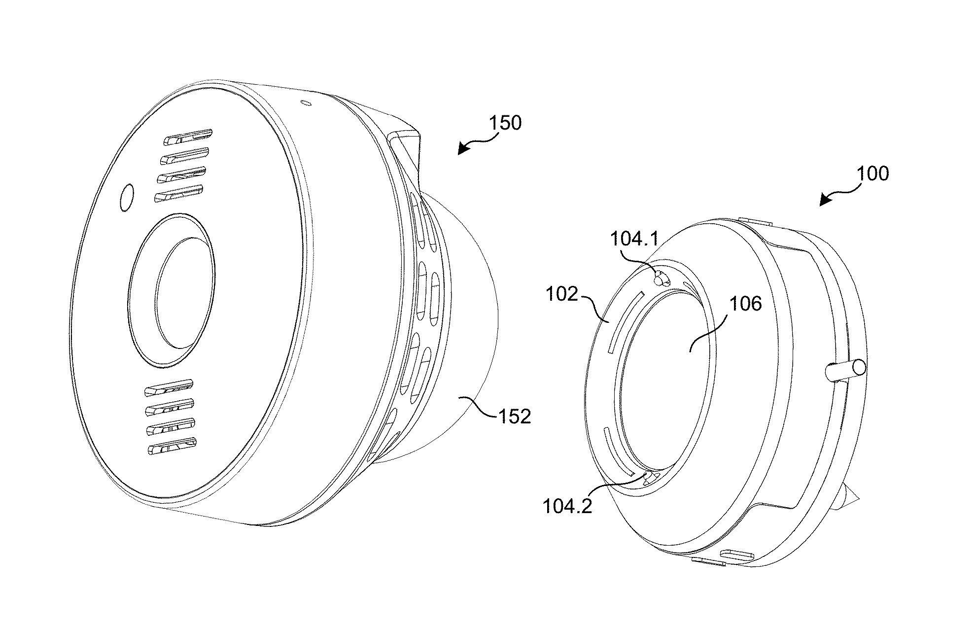
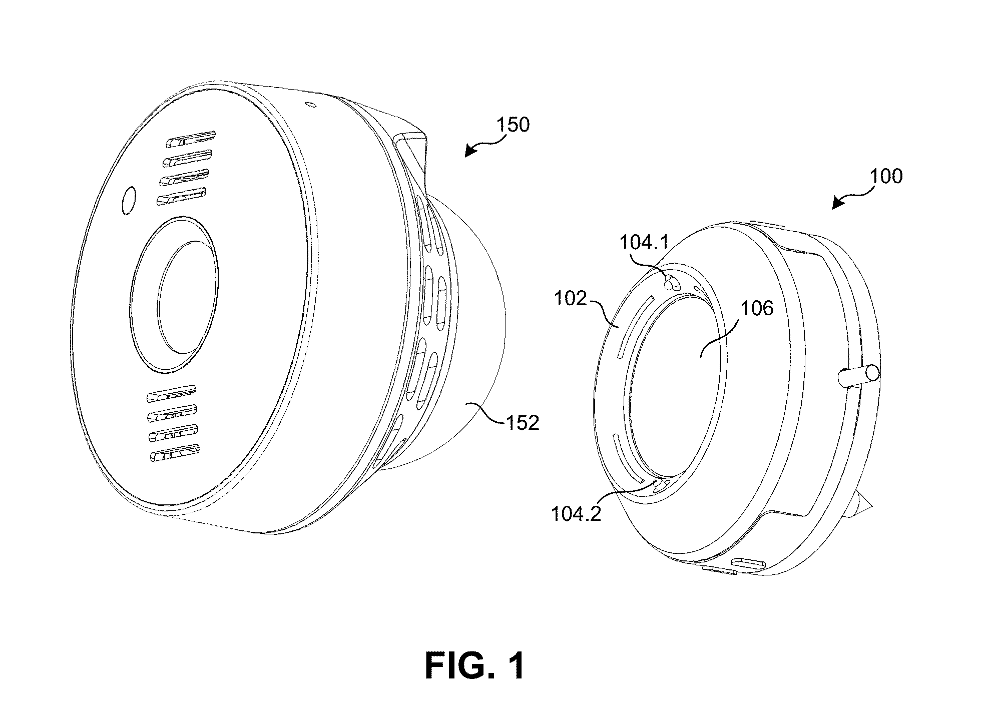
[0095]Embodiments of the present invention provide a micro camera and power connector that solve the problem of adjusting a directional angle and / or a rotational angle of the camera mounted on a surface of the power connector. The connector base can serve as a device mount and power source for various types of devices that can be mounted on the con...


PUM


Abstract

A power connector facilitates mounting and repositioning an electronic device via a magnetic field. The power connector can include a receptacle surface comprising a curved surface operable to mate with a curved contact surface of an electronic device, and a device-coupling mechanism operable to hold the curved contact surface of the electronic device pressed against the curved surface of the power connector device, while an angle of the electronic device changes with respect to the power connector. The power connector can also include a power-transfer mechanism operable to transfer at least power to the electronic device, without an electrical wire between power connector and the electronic device, while the angle of the electronic device changes with respect to the power connector.

Description

RELATED APPLICATION[0001]This application claims the benefit of:[0002]U.S. Provisional Application No. 62 / 073,892, entitled “Power Connector,” by inventors Gerardo G. Huerta and Ming-Tsung Su, filed 31 Oct. 2014; and[0003]U.S. Provisional Application No. 62 / 152,673, Attorney Docket Number UBNT15-1001PSP, entitled “POWER CONNECTOR,” by inventors Gerardo G. Huerta and Ming-Tsung Su, filed 24 Apr. 2015,the disclosures of which are incorporated herein in their entirety.BACKGROUND[0004]1. Field[0005]This disclosure is generally related to a power connector. More specifically, this disclosure is related to a receptacle which facilitates mounting an electronic device on the receptacle via a magnetic field.[0006]2. Related Art[0007]Consumer and commercial electronic devices oftentimes receive direct current (DC) power from an external power supply which transforms a conventional alternating current (AC) power supply to a DC power signal that meets the electronic device's power requirements....

Claims


Application Information

Patent Timeline
Patent Type & Authority Applications(United States)
IPC IPC(8): H04N5/232H01R39/64H04N5/225H01R13/62
CPCH04N5/23241H01R13/6205H04N5/23206H04N5/2252H04N5/2253H01R39/643H01F7/0252H01F38/14H01R35/04H04N23/51H04N23/54
Inventor HUERTA, GERARDO G.SU, MING-TSUNG
Owner UBIQUITI INC
Why Eureka
Try Eureka