Systems and Methods for Intra-Operative Image Analysis

a system and image technology, applied in the field of intraoperative image analysis, can solve the problems of limited adoption of systems, affecting patient satisfaction and implant longevity, and surgeons that do not use systems, so as to improve the outcome of bone repositioning, fracture repair, and/or fixation within a patient, accurate estimation

Active Publication Date: 2016-05-12
DEPUY SYNTHES PROD INC
View PDF6 Cites 16 Cited by
  • Summary
  • Abstract
  • Description
  • Claims
  • Application Information

AI Technical Summary

Benefits of technology

[0010]Another object of the present invention is to provide image analysis and feedback information to enable better fracture reduction and / or optimal implant selection during the surgery.
[0012]A still further object of the present invention is to improve the outcome of bone repositioning, fracture repair, and / or fixation within a patient.
[0013]This invention results from the realization that postoperative change in offset and leg length can be accurately estimated during surgery by overlaying or otherwise comparing preoperative and intraoperative images that have been consistently scaled based on pelvic anatomy, generating consistent femoral landmarks in each image, and calculating the vector difference between femoral landmarks after correcting for possible differences in femoral positioning between the two images relative to the pelvis.

Problems solved by technology

Despite obvious clinical benefit, these systems have had limited adoption due to their expense, the learning curve and training requirements for surgeons and, for some systems, the additional procedure and time associated with hardware insertion into the patient.
Surgeons that do not use these systems are limited to traditional techniques that are generally based on visual analysis and surgeon experience.
However, these techniques are inconsistent, often leading to outliers in functional parameters which may affect patient satisfaction and implant longevity.
The intra-operative technique described by Matta et al. is time-consuming and has a high risk of inaccuracy due to differences in rotation, magnification and / or scaling of various images, because the technique relies upon acquiring a preoperative and intraoperative image that are scaled and positioned equivalently.
Maintaining femoral position while performing hip arthroplasty can pose a significant and often unrealistic challenge to a surgeon that is focused on performing a procedure.
The high risk of inaccurate interpretation using this technique has limited its utility in guiding surgical decision making.
While the use of a computer system may facilitate some aspects of this technique, the underlying challenges to the technique are consistent with the challenges to Matta's approach, and limit the system's potential utility.

Method used


Image

  • Systems and Methods for Intra-Operative Image Analysis
  • Systems and Methods for Intra-Operative Image Analysis
  • Systems and Methods for Intra-Operative Image Analysis

Examples


Embodiment Construction

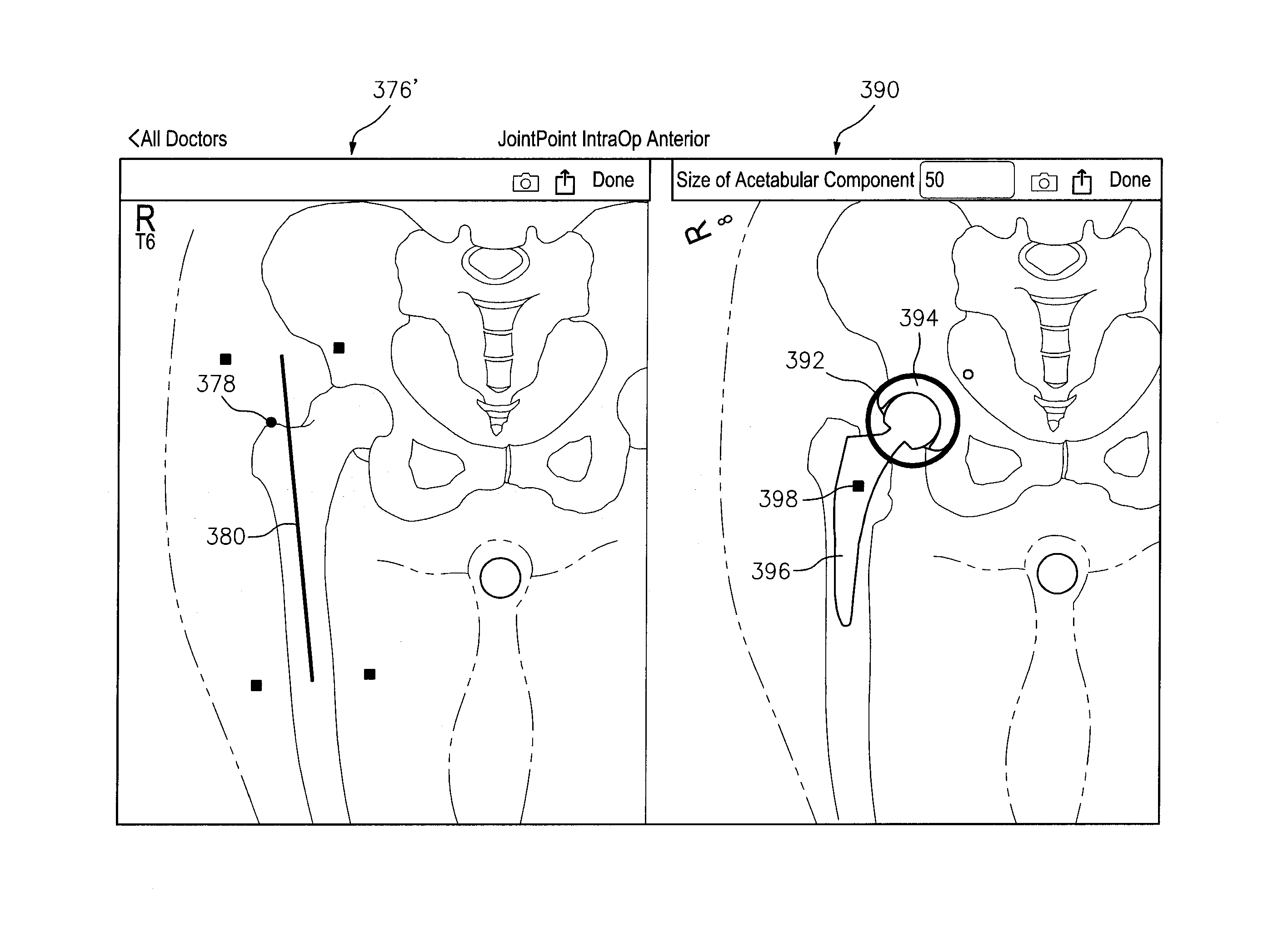
[0045]This invention may be accomplished by a system and / or method that acquire (i) at least one reference image including one of a preoperative image of a surgical site with skeletal and articulating bones and a contralateral image on an opposite side of the patient from the surgical site, and (ii) at least one intraoperative image of the site after an implant has been affixed to the articulating bone. The reference and intraoperative images are received and at least one reference landmark point is generated on at least one anatomical feature on the articulating bone, such as on the greater trochanter of a femur, in the reference image and at least one intraoperative landmark point on that anatomical feature in the intraoperative image. At least the first center of rotation of the implant is estimated in at least one of the reference image and the intraoperative image, and the longitudinal axis of the articulating bone is identified in each of the reference image and intraoperative...


PUM


Abstract

A system and method that acquire (i) at least a reference image including one of a preoperative image of a surgical site with skeletal and articulating bones and a contralateral image on an opposite side of the patient from the surgical site, and (ii) at least an intraoperative image of the site after an implant has been affixed to the articulating bone. The system generates at least one reference landmark point on at least one anatomical feature on the articulating bone in the reference image and at least one intraoperative landmark point on that anatomical feature in the intraoperative image. The reference and intraoperative images are compared, and differences between the orientation of the articulating bone in the two images are utilized to analyze at least one of offset and length differential.

Description

CROSS-REFERENCE TO RELATED APPLICATION[0001]This application is a continuation-in-part application of U.S. patent application Ser. No. 14 / 630,300 filed 24 Feb. 2015, also referred to as “parent application”, and claims priority to U.S. Provisional Application No. 61 / 944,520 filed 25 Feb. 2014, U.S. Provisional Application No. 61 / 948,534 filed 5 Mar. 2014, U.S. Provisional Application No. 61 / 980,659 filed 17 Apr. 2014, U.S. Provisional Application No. 62 / 016,483 filed 24 Jun. 2014, U.S. Provisional Application No. 62 / 051,238 filed 16 Sep. 2014, U.S. Provisional Application No. 62 / 080,953 filed 17 Nov. 2014, and U.S. Provisional Application No. 62 / 105,183 filed 19 Jan. 2015. This application is also related to U.S. patent application Ser. No. 14 / 974,225, filed 18 Dec. 2015, by the present inventors. The entire contents of each of the above applications are incorporated herein by reference.FIELD OF THE INVENTION[0002]The invention relates to analysis of images of features within a pati...

Claims


Application Information

Patent Timeline
Patent Type & Authority Applications(United States)
IPC IPC(8): A61B6/12A61B6/00
CPCA61B6/12A61B6/505A61B6/5235A61B2034/2068A61B6/463A61B6/467A61B6/5217A61B34/10A61B2034/108G06T2207/10116G06T2207/30052G06T2207/30008G06T7/0012G06T7/60G06T2207/20092G16H30/40G16H20/40G16H40/63G06T7/33G06T7/0014
Inventor WOLLOWICK, NOAH D.COOPER, ANDREW J.
Owner DEPUY SYNTHES PROD INC
Why Eureka
Try Eureka