Systems and methods for intra-operative image analysis

a system and image technology, applied in the field of image analysis, can solve the problems of/or perform calculations, inconvenient operation, and inability to accurately analyze preoperative scaling techniques, etc., and achieve the effect of accurately and effectively analysing and/or performing calculations

Active Publication Date: 2019-10-08
DEPUY SYNTHES PROD INC
View PDF27 Cites 7 Cited by
  • Summary
  • Abstract
  • Description
  • Claims
  • Application Information

AI Technical Summary

Benefits of technology

[0013]An object of the present invention is to provide a system and method to accurately and effectively analyze and / or perform calculations on images of anatomical features and / or implants such as prosthetic devices during surgery.
[0014]Another object of the present invention is to provide image analysis and feedback information to enable more accurate planning, better fracture reduction, and / or optimal implant selection during the surgery.
[0016]A still further object of the present invention is to improve the outcome of bone repositioning, fracture repair, and / or fixation within a patient.
[0017]This invention results from the realization that offset and length differential of an implant having at least one center of rotation can be accurately estimated during surgery by establishing at least one stationary point on the skeletal bone and at the center of rotation in an intraoperative image, aligning a digital implant representation with the implant, and then copying and positioning the digital representation in at least one reference image including one of (a) a preoperative image of the surgical site and (b) a contralateral image on an opposite side of the patient from the surgical site. Another realization is that changes in offset and length differential can be estimated based on selected alternative changes in at least one dimension of the implant for potential alternative implants.
[0021]In some embodiments, the reference and intraoperative images are provided by the image selection module to the data input module in a digitized format. In certain embodiments, the templating module positions the first digital representation in the reference image relative to the reference stationary point according to at least an intraoperative vector calculation utilizing at least the intraoperative stationary point relative to the first center of rotation and a reference vector calculation utilizing at least the reference stationary point relative to the first center of rotation. In one embodiment, the reference vector calculation replicates the intraoperative vector calculation. In a number of embodiments, the landmark identification module further generates at least a reference landmark point on at least one anatomical feature on the articulating bone in the reference image and at least an intraoperative landmark point on at least that anatomical feature on the articulating bone in the intraoperative image and, in one embodiment, at least one of the templating module and the analysis module utilizes the landmark points to assist alignment of the second digital implant representation on the articulating bone in both of the reference and intraoperative images.

Problems solved by technology

There are benefits to both of these technologies, but each has respective limitations.
This preoperative scaling technique has inherent limitations to accuracy because it assumes that the bones within a patient and the surface ball marker will magnify at the same ratio.
Commonly, the surgeon will realize during the surgery that this scale factor is inaccurate, due to deviations in magnification ratios, rendering the preoperative template ineffective for intraoperative decision making.
For emergency cases such as hip fractures, preoperative digital templating often cannot be utilized, because the X-ray images are taken in a hospital setting without utilizing a ball marker or other scaling device.
Despite obvious clinical benefit, these systems have had limited adoption due to their expense, the learning curve and training requirements for surgeons and, for some systems, the additional procedure and time associated with hardware insertion into the patient.
These adoption barriers have limited the use of computer assisted navigation to an extremely small percentage of overall hip arthroplasty surgeries.
The surgeons that do not use these systems are limited to traditional techniques that are generally based on visual analysis and surgeon experience.
However, these techniques are inconsistent, often leading to outliers in functional parameters which may affect patient satisfaction and implant longevity.
The intra-operative technique described by Matta et al. is time-consuming and has a high risk of inaccuracy due to differences in rotation, magnification and / or scaling of various images.
The high risk of inaccurate interpretation using this technique has limited its utility in guiding surgical decision making.
While the use of a computer system may facilitate some aspects of this technique, the underlying challenges to the technique are consistent with the challenges to Matta's approach, and limit the system's potential utility.
The selection of the proper implant and associated neck-shaft angle is often incompletely evaluated by the surgeon and implant representative utilizing conventional techniques.
Furthermore, variations in placement of screws and other fixation devices and implants can significantly alter patient outcomes in treatment of these fractures.
Proper reduction of fractures, that is, proper alignment of bones during surgery, often leads to more consistent patient outcomes, and intraoperative analysis of such reductions is incompletely evaluated currently because of the lack of non-invasive technologies that enable intraoperative analysis.
Currently, intraoperative images are utilized by surgeons, but there is no ability to readily analyse these parameters and form comparative analysis to normal anatomy.

Method used


Image

  • Systems and methods for intra-operative image analysis
  • Systems and methods for intra-operative image analysis
  • Systems and methods for intra-operative image analysis

Examples


Embodiment Construction

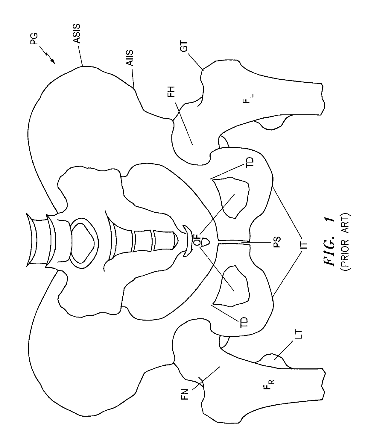
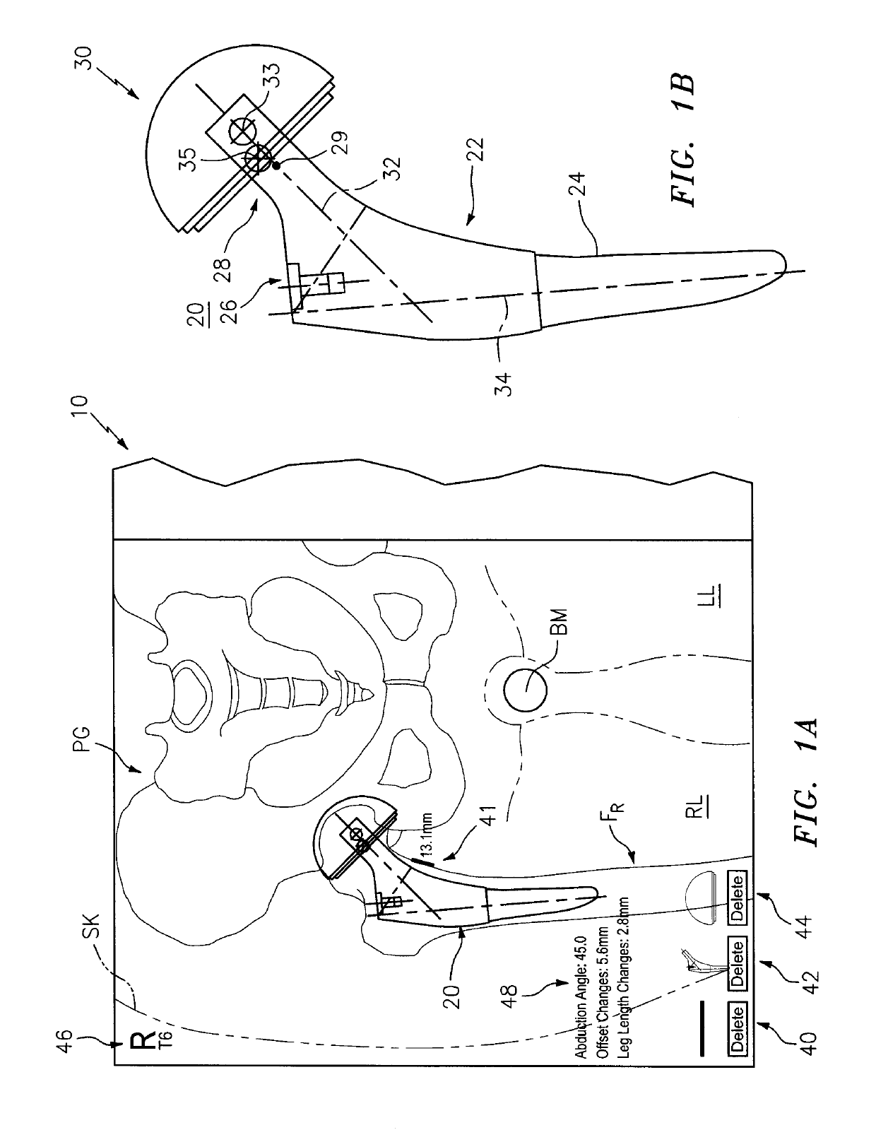
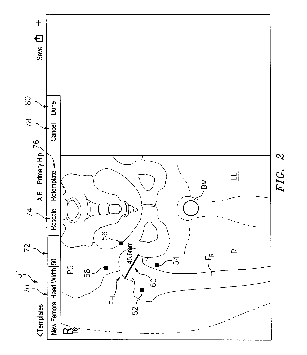
[0114]This invention may be accomplished by a system and method that acquire (i) at least one reference image including one of a preoperative image of a surgical site with skeletal and articulating bones and a contralateral image on an opposite side of the patient from the surgical site, and (ii) at least one intraoperative image of the site after an implant has been affixed to the articulating bone. In certain constructions, the system generates at least one reference stationary point on at least the skeletal bone in the reference image and at least one intraoperative stationary point on at least the skeletal bone in the intraoperative image. The location of the implant is identified in the intraoperative image, preferably including the position of first and second centers of rotation which are co-located in the intraoperative image. At least one of (i) a first digital implant representation is aligned with the skeletal component and with at least the intraoperative stationary poin...


PUM


Abstract

A system and method that acquire (i) at least a reference image including one of a preoperative image of a surgical site with skeletal and articulating bones and a contralateral image on an opposite side of the patient from the surgical site, and (ii) at least an intraoperative image of the site after an implant has been affixed to the articulating bone. The system preferably generates at least one reference stationary point on at least the skeletal bone in the reference image and at least one intraoperative stationary point on at least the skeletal bone in the intraoperative image. The location of the implant is identified in the intraoperative image, preferably including the position of first and second centers of rotation, which are digitally represented and copied into the reference image to analyze at least one of offset and length differential.

Description

CROSS-REFERENCE TO RELATED APPLICATION[0001]This application is a continuation-in-part application of U.S. patent application Ser. No. 14 / 630,300 filed 24 Feb. 2015, also referred to as “parent application”, and claims priority to U.S. Provisional Application No. 61 / 944,520 filed 25 Feb. 2014, U.S. Provisional Application No. 61 / 948,534 filed 5 Mar. 2014, U.S. Provisional Application No. 61 / 980,659 filed 17 Apr. 2014, U.S. Provisional Application No. 62 / 016,483 filed 24 Jun. 2014, U.S. Provisional Application No. 62 / 051,238 filed 16 Sep. 2014, U.S. Provisional Application No. 62 / 080,953 filed 17 Nov. 2014, and U.S. Provisional Application No. 62 / 105,183 filed 19 Jan. 2015, all of which are incorporated by reference herein in their entireties.FIELD OF THE INVENTION[0002]The invention relates to analysis of images of features within a patient and more particularly to accurately analyzing such images during surgery.BACKGROUND OF THE INVENTION[0003]Orthopedic surgeons and other healthca...

Claims


Application Information

Patent Timeline
Patent Type & Authority Patents(United States)
IPC IPC(8): A61B34/20A61B34/10G06T7/33G06T7/00A61B6/00A61B6/12A61B90/00
CPCA61B6/505A61B34/20A61B34/10A61B6/12A61B6/463A61B6/5235G06T7/0014G06T7/33A61B2034/2074A61B2034/2065A61B2090/363A61B2034/108G06T2207/30052G06T2207/30008G06T2207/10116A61B2090/364G16H40/63G16H20/40G16H30/40
Inventor WOLLOWICK, NOAH D.COOPER, ANDREW J.
Owner DEPUY SYNTHES PROD INC
Why Eureka
Try Eureka