Scaffold implant system

a technology of implant system and screw, which is applied in bone implant, medical science, dentistry, etc., can solve the problems of limiting or preventing the use of implants, methods, and serious drawbacks, and achieves the effects of reducing the risk of fracture, increasing the cost, and increasing the morbidity and inconvenience of patients

Inactive Publication Date: 2016-05-12
YAKIR MEIR +1
View PDF21 Cites 7 Cited by
  • Summary
  • Abstract
  • Description
  • Claims
  • Application Information

AI Technical Summary

Benefits of technology

[0066]In the case of screw-threaded implants, a predetermined torque is used in order to achieve stable insertion of the implant fixture within the bone block. One significant advantage of the present invention in relation to prior art products and methods is that this insertion process is performed in a controlled environment, wherein precisely the correct amount of torque force may be applied in order to achieve the desired result. This is in marked contrast to the prior art techniques, in which the implant fixture is inserted and stabilized within the bone block after the latter has been implanted within the patient's mouth. Such prior art methods clearly pose significant problems with regard to the insertion of screw-threaded implants (and also of other forms of implant) into the bone block, including, for example the dislodgement of the bone block from its augmented position when forces are applied thereon in order to stabilize the implant fixture. The present invention provides a novel and inventive solution to these problems.
[0067]In some embodiments of the present invention, the implant fixture may be secured to the bone block with a screw.
[0068]The scaffold implant (i.e. the combination of the implant fixture and bone block) is implanted by the clinician into the intended working site as a single, integral unit.
[0069]At the time of implantation the intended site in the mandible or maxilla is prepared for receiving the scaffold implant according to the shape and size of the bone block, the implant fixture (for the partially embedded type), and the shape of the alveolar ridge. The scaffold implant is placed in contact with the patient's bone surface of the osteotomy site and secured in place by means of any suitable method, as well known in the art, including (but not limited to) mechanical contact, membrane, bone screws, tacks, biological glue or titanium pins.
[0070]In some preferred embodiments, the bone block may be further stabilized with either a ring-shaped extension from the implant fixture body or a channel within the implant fixture body, both of which structures provide an aperture for receiving a bone screw. Thus, in one embodiment, the bone screw is placed through the bone block, into the implant fixture extension ring or channel and then into the patient's bone. A predetermined channel is made in the bone block to receive the bone screw and to guide it through the implant fixture channel or extension ring. FIG. 9 shows an example of a fully-embedded scaffold implant 90 of the present invention fitted with an extension ring 92, passing from the titanium implant fixture 94 into bone block 96. The figure also shows two bone screw apertures 98, each of which represents the lateral openings of a bone screw channel.
[0071]A sagittal section of a similar embodiment is illustrated in FIG. 10. In the scaffold implant 100 shown in this figure, a long bone screw is seen passing sequentially (from the buccal to lingual side) through the thickness of bone block 104, a channel in screw-thread implant fixture 106. The remaining distal portion of the bone screw thread (i.e. the length of the bone screw thread that emerges from the second side of the implant fixture is intended to be used to secure the entire scaffold implant 100 into the patient's mandibular or maxillary bone.

Problems solved by technology

There are, however, certain technical and clinical problems which limit or prevent the use of implants in some circumstances.
These methods, however, suffer from a number of serious drawbacks.
Firstly, the patient is required to make multiple visits, often separated by several weeks or months, in order to undergo the various steps of the augmentation and implantation procedures.
Such multiple treatment steps increase the cost, morbidity and inconvenience to the patient.
Another—and perhaps even more serious—problem associated with these prior art solutions is the poor mechanical stability of the titanium implant when using particulate bone substitute material or within the bone blocks.
This problem arises from the fact that said implant is inserted by the clinician into the bone block in situ, within the patient's mouth.
Not only is access to the block restricted (since it has already been implanted within the patient's maxillary or mandibular bone), but the magnitude of mechanical force (e.g. torque forces, in the case of screw-threaded implants) that may be applied by the clinician is obviously very limited.
This is time consuming and technique sensitive.
Less than optimum stability of the implant fixture within the implanted bone block will obviously result in poor functioning of the dentition, as well as a significantly-reduced success rate for the implant.
Similarly, in the field of orthopedic implants—and in particular, spinal implants—the prior art systems and methods are limited in their application and effectiveness by problems associated with the need for replacement bone blocks to be manipulated at the operating site.

Method used


Image

  • Scaffold implant system
  • Scaffold implant system
  • Scaffold implant system

Examples


example 1

Preparation of a Scaffold Implant System using a Bovine Bone Block

[0094]One embodiment of the scaffold implant device of the present invention may be prepared using a bovine bone block. A suitably-sized bone piece is obtained and then processed and decontaminated in the usual manner rendering it suitable condition for augmentation in the human body. In the present example, the bovine bone block is obtained from a commercial supplier (for example Bio-Oss by Geistlich Germany or SmartBone by IBI, Switzerland).

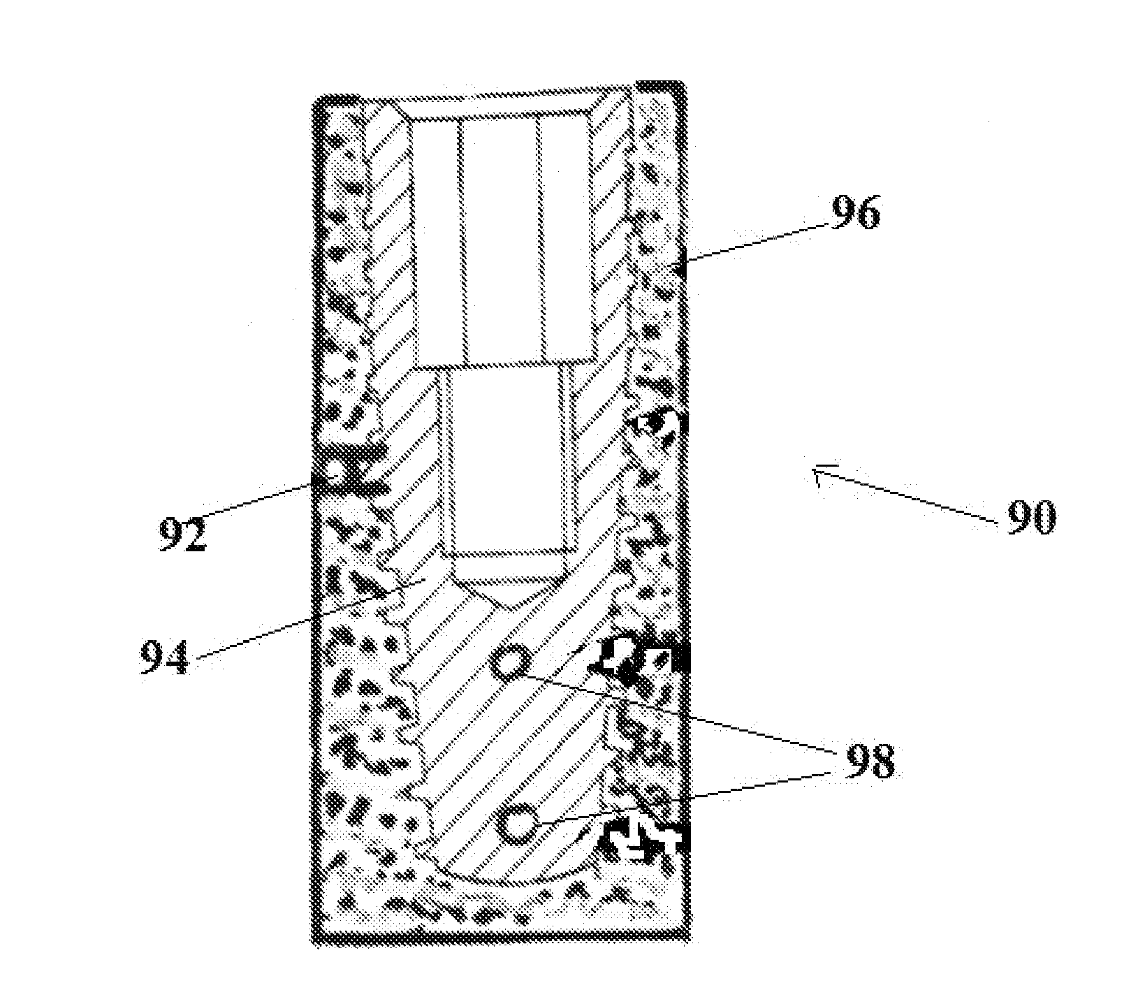
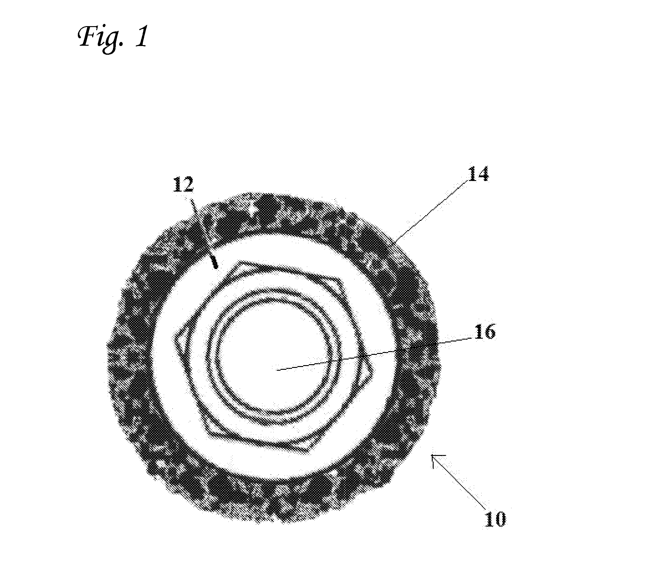
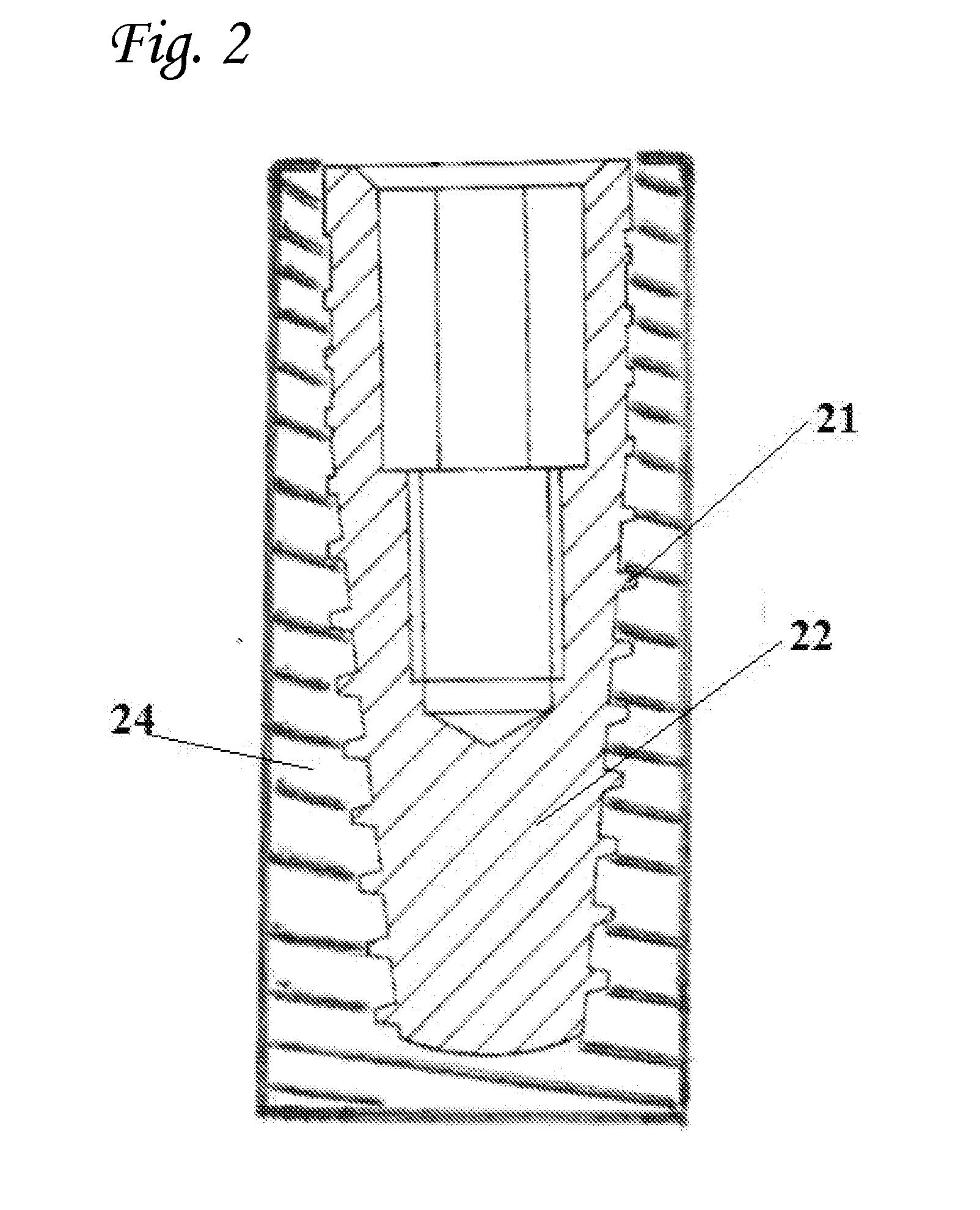
[0095]The bone block is cut and trimmed into a specific shape using CNC technology. The external shape of the block is cylindrical having a diameter of 7.5 mm and a length of 11.5 mm in length.

[0096]A longitudinal hole, having a diameter of 4.2 mm and a length of 10 mm is drilled in the middle of the cylinder from the top, downwards.

[0097]A longitudinal portion of the block is removed from its base. The length of the removed portion is 8.5 mm. The 3.0 mm of the upper part of the ...

example 2

Implantation of a Bovine Bone Block Scaffold Implant System

[0103]The dentist prepares an osteotomy site by exposing the alveolar bone. Using a dental drill with a diameter of 4.2 mm and length of 7.0 mm a longitudinal concavity having a depth of 2.1 mm and a length of 7.0 mm is cut into the bone. The concavity begins at the marginal ridge and continues toward the basal bone.

[0104]A scaffold implant device (prepared as described in Example 1, hereinabove) is inserted in the concavity by placing the exposed dental fixture portion in tight contact with the alveolar ridge bone. The 3.0 mm length of the upper part of the device is positioned on top of the alveolar ridge.

[0105]A bone screw (Surgidoc, United Kingdom) is used to secure the device to the alveolar ridge. It is placed through the horizontal hall in the bone block continuing through the horizontal hole in the implant fixture and into the alveolar ridge to a depth of about 5.0 mm. The bone screw is then torqued into its place wi...

example 3

Scaffold Implant Mesh Device

[0106]The Scaffold implant mesh device is constructed from a titanium fixture and bone block.

[0107]The titanium fixture sprawls over the entire Scaffold implant space in a 3D mesh like structure (e.g. honeycomb shape). The titanium mesh can include different types of restorative connections (e.g. internal hexagon, external hexagon connection).

[0108]The titanium restorative connections will be positioned at the flat upper portion of the implant, ready to accept the prosthodontic restoration.

[0109]The titanium mesh is manufactured using an NC technique as a single unit that includes a mesh titanium fixture with restorative connections.

[0110]The Scaffold implant mesh device is surrounded by 1.5 mm depth of bone material forming a floor and walls around the mesh fixture and open at the top (e.g. forming an envelope-like structure). The bone material used may be of any suitable source, such as xenograft, allograft or alloplast, and is formed into its final sha...


PUM


Abstract

The present invention is directed to isolated scaffold implant system comprising a stable combination of an implant fixture and a bone block, wherein said stable combination is suitable in size and form to be implanted within a prepared site in a subject's bone. The scaffold implant system of the present invention is particularly suitable for use in dental implant techniques.

Description

FIELD OF THE INVENTION[0001]The present invention is directed to an implant system that is suitable for dental and surgical use. More specifically, the present invention relates to a highly stable bone block-implant fixture combination that may be used in a variety of dental and orthopedic implant procedures.BACKGROUND OF THE INVENTION[0002]The use of dental implants in order to replace missing teeth has increased greatly in recent years. There are, however, certain technical and clinical problems which limit or prevent the use of implants in some circumstances. In particular, the insertion of dental implants into portions of the mandible or maxilla in which there has been bone loss often requires multiple procedures in order to prepare a stable implantation site. Similarly, additional preparatory techniques may also be required in cases wherein anatomical or pathological features of the adjoining sinuses result in the need for procedures that augment the amount of bone in the maxil...

Claims


Application Information

Patent Timeline
Patent Type & Authority Applications(United States)
IPC IPC(8): A61F2/28A61F2/30A61C8/00A61F2/44
CPCA61F2/2803A61F2/28A61F2/44A61F2002/2835A61C8/0078A61C8/0022A61C8/0019A61F2/3099A61C8/0009A61C8/0012A61C8/0018A61C8/0068
Inventor YAKIR, MEIRGUREWITZ, LOTAN
Owner YAKIR MEIR
Why Eureka
Try Eureka