Microphone With Electronic Noise Filter

a technology of electronic noise filter and microphone, applied in the field of microphones, can solve the problems of poor low frequency response, potential inability to hear or recognize the received signal, and large nois

Inactive Publication Date: 2016-05-12
KNOWLES ELECTRONICS INC
View PDF4 Cites 25 Cited by
  • Summary
  • Abstract
  • Description
  • Claims
  • Application Information

AI Technical Summary

Problems solved by technology

Some environments can be quiet, while others have considerable noise.
If nothing is done to negate the noise, the received signal will potentially not be heard or recognized by a listener.
Previous filters were always activated and were always applied to all signals resulting in poor low frequency responses and, in some cases, higher self-noise of th

Method used


Image

  • Microphone With Electronic Noise Filter
  • Microphone With Electronic Noise Filter
  • Microphone With Electronic Noise Filter

Examples


Embodiment Construction

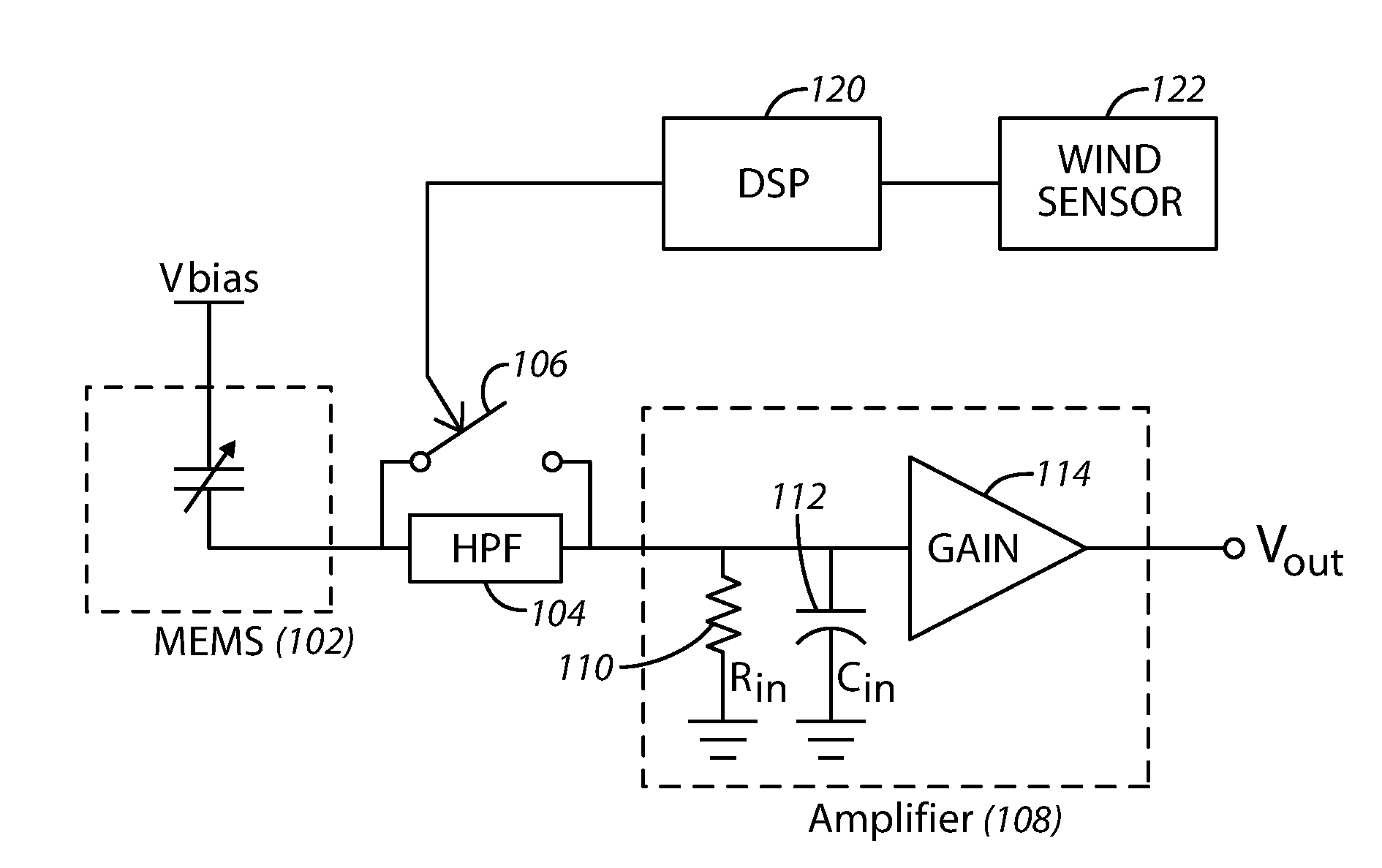
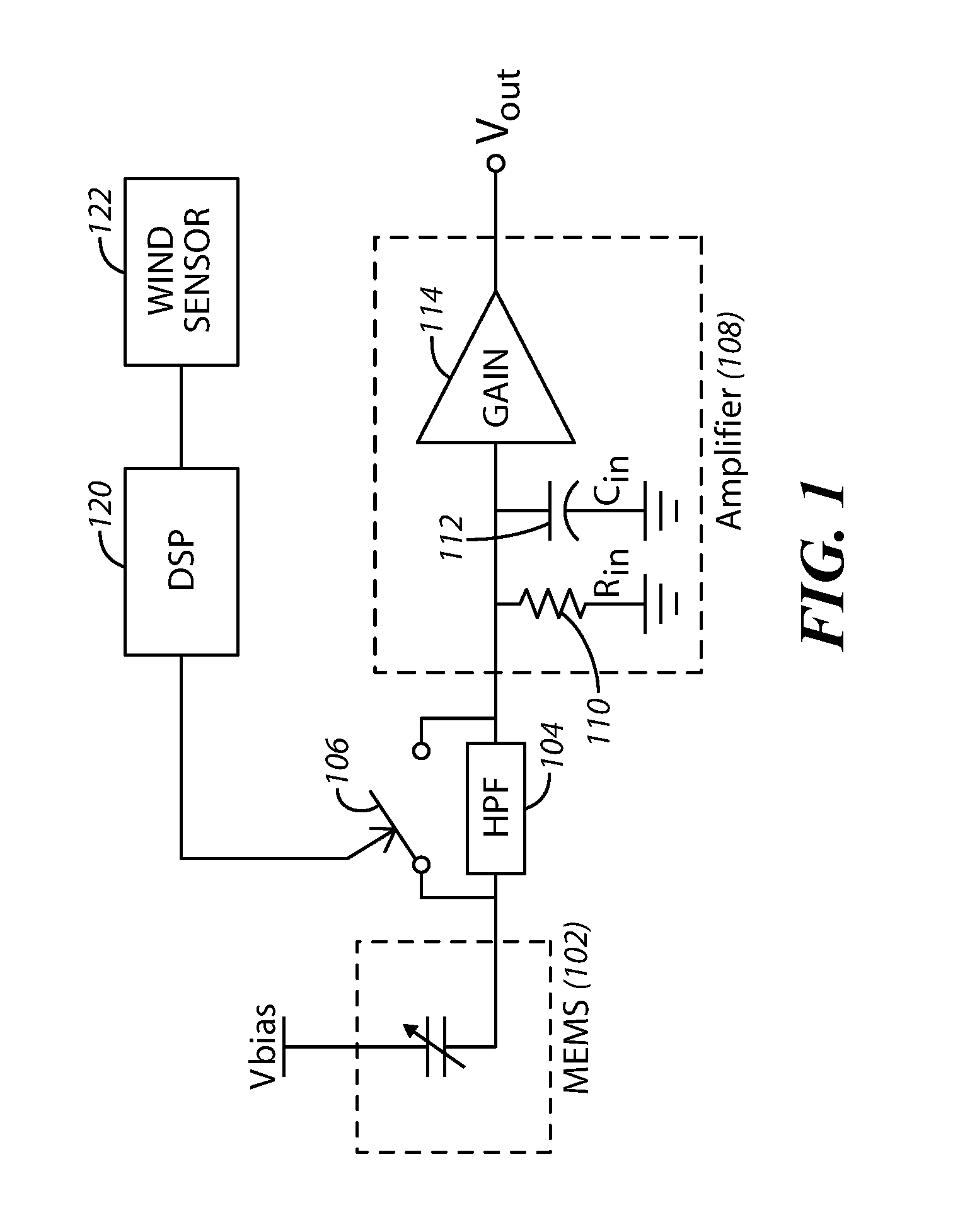
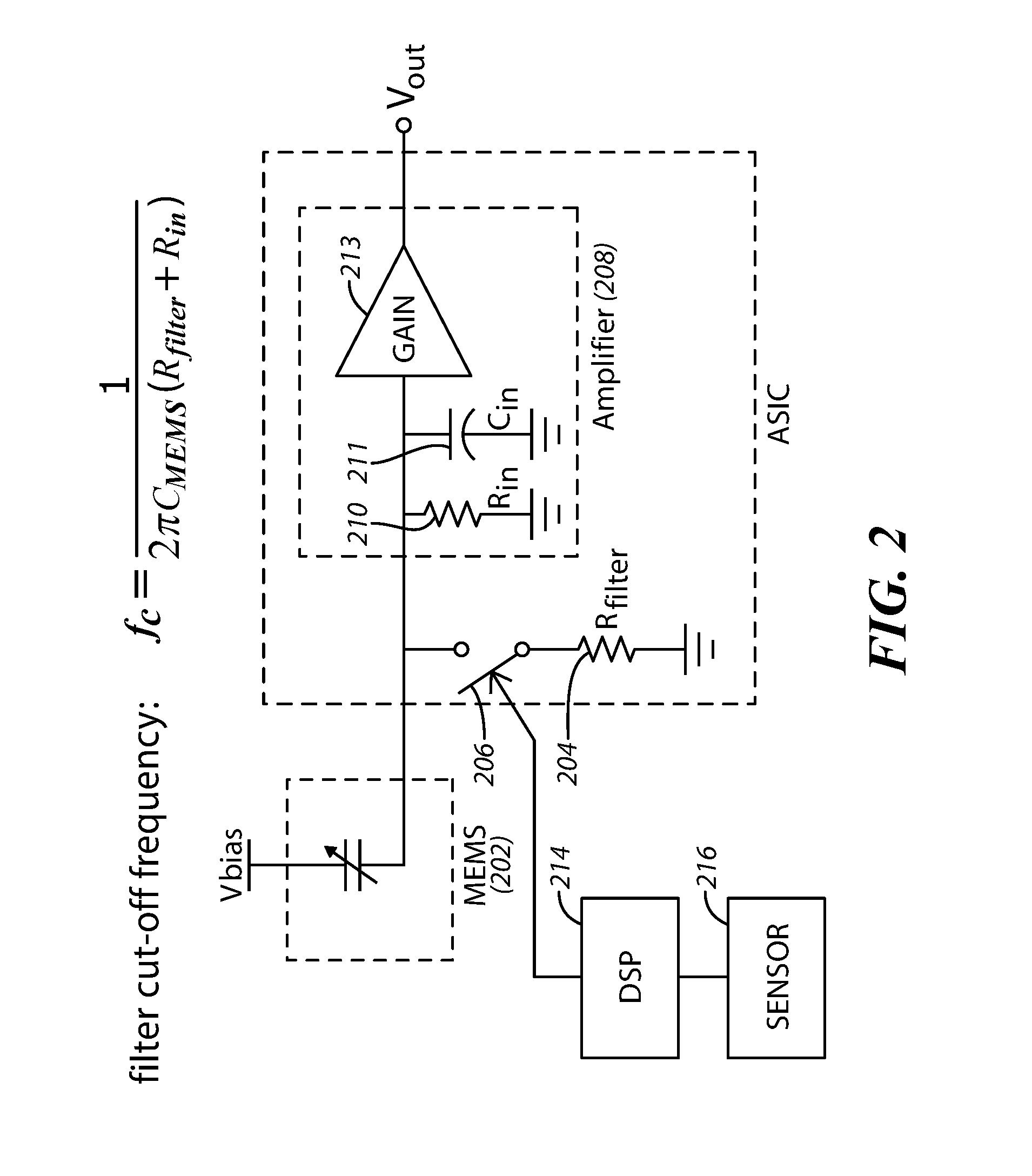
[0015]The present approaches provide a switchable passive filter that is utilized before amplification of a received signal occurs. By “passive,” it is meant non-active components such as resistors and capacitors are utilized. In other embodiments, active components may be used. For example, a switchable active filter at the input of the microphone is provided. In one aspect, a micro-electro-mechanical System (MEMS) device receives a signal from a microphone. A switchable high pass filter (for example) is selectively utilized to act on the signal (or not act on the signal) before the signal is sent to an amplifier for further processing. The filter is only engaged in the circuit when wind noise (or other types of noise) is present. In one approach, a DSP may receive readings from an external wind velocity sensor or other wind sensing (or measuring) device. A signal is transmitted from the DSP to the switch that will either include or exclude the filter from the circuit based upon wh...


PUM


Abstract

An acoustic apparatus includes a microelectromechanical system (MEMS) device, a controlled filter coupled to the MEMS device, and an amplifier. The controllable filter and the amplifier are coupled together at a node. A cut-off frequency of the filter is selectable based upon reception or non-reception of a low frequency audio signal by the acoustic apparatus.

Description

CROSS-REFERENCE TO RELATED APPLICATION[0001]This patent claims benefit under 35 U.S.C. §119(e) to U.S. Provisional Application No. 62078131 entitled “Microphone with electronic noise filter” filed Nov. 11, 2014, the content of which is incorporated herein by reference in its entirety.TECHNICAL FIELD[0002]This application relates to microphones and mitigating or eliminating noise concerns associated with these devices.BACKGROUND OF THE INVENTION[0003]Microphones are used to obtain sound energy and convert the sound energy into electrical signals. Once obtained, the electrical signals can be processed in a number of different ways.[0004]One example of a microphone is a Micro-Electro-Mechanical System (MEMS) microphone. MEMS microphones are typically composed of two main components: a MEMS device (including a diaphragm and a back plate) that receives and converts sound energy into an electrical signal, and an Application Specific Integrated Circuit (ASIC) (or other circuits such as buf...

Claims


Application Information

Patent Timeline
IPC IPC(8): G10L21/0232H03F3/183H04R3/06H04R19/00H04R19/04
CPCG10L21/0232H04R19/005H04R19/04H03F2200/372H03F3/183H03F2200/03H03F2200/165H04R3/06H03F3/187
Inventor KUNTZMAN, MICHAEL
Owner KNOWLES ELECTRONICS INC
Why Eureka
Try Eureka