Roof Attachment Flashing Assembly

a technology for roofs and flashing assemblies, applied in the direction of heat collector mounting/support, building repairs, lighting and heating equipment, etc., can solve the problems of too complicated installation, unsatisfactory, and more expensive to manufactur

Inactive Publication Date: 2016-05-12
IRONRIDGE
View PDF14 Cites 40 Cited by
  • Summary
  • Abstract
  • Description
  • Claims
  • Application Information

AI Technical Summary

Benefits of technology

[0011]It is an object of this invention to provide a roof flashing assembly that prevents external liquids from entering the roof structure where the flashing is secured to the roof without using additional liquid sealants on the lower surface of the flashing.
[0012]It is an object of this invention to provide a flashing assembly with a rubber seal in combination with a disk below the raised portion that prevents external liquids from entering the roof structure where the flashing is fastened to the roof.
[0013]It is an object of this i

Problems solved by technology

Existing prior art flashing assembly designs are either unsatisfying in providing an adequate seal to prevent water from seeping into holes created while securing the flashing to the roof, are too complicated to install, or require too many individual parts making them more expensive to manufacture.
Having to pre-treat a flashing is time consuming and may cause the flashing to be inconsistently sealed to the roof and cause leaking.
But at best, the location of the block may only possibly prevent water from entering at the top of the block.
This

Method used


Image

  • Roof Attachment Flashing Assembly
  • Roof Attachment Flashing Assembly
  • Roof Attachment Flashing Assembly

Examples


Embodiment Construction

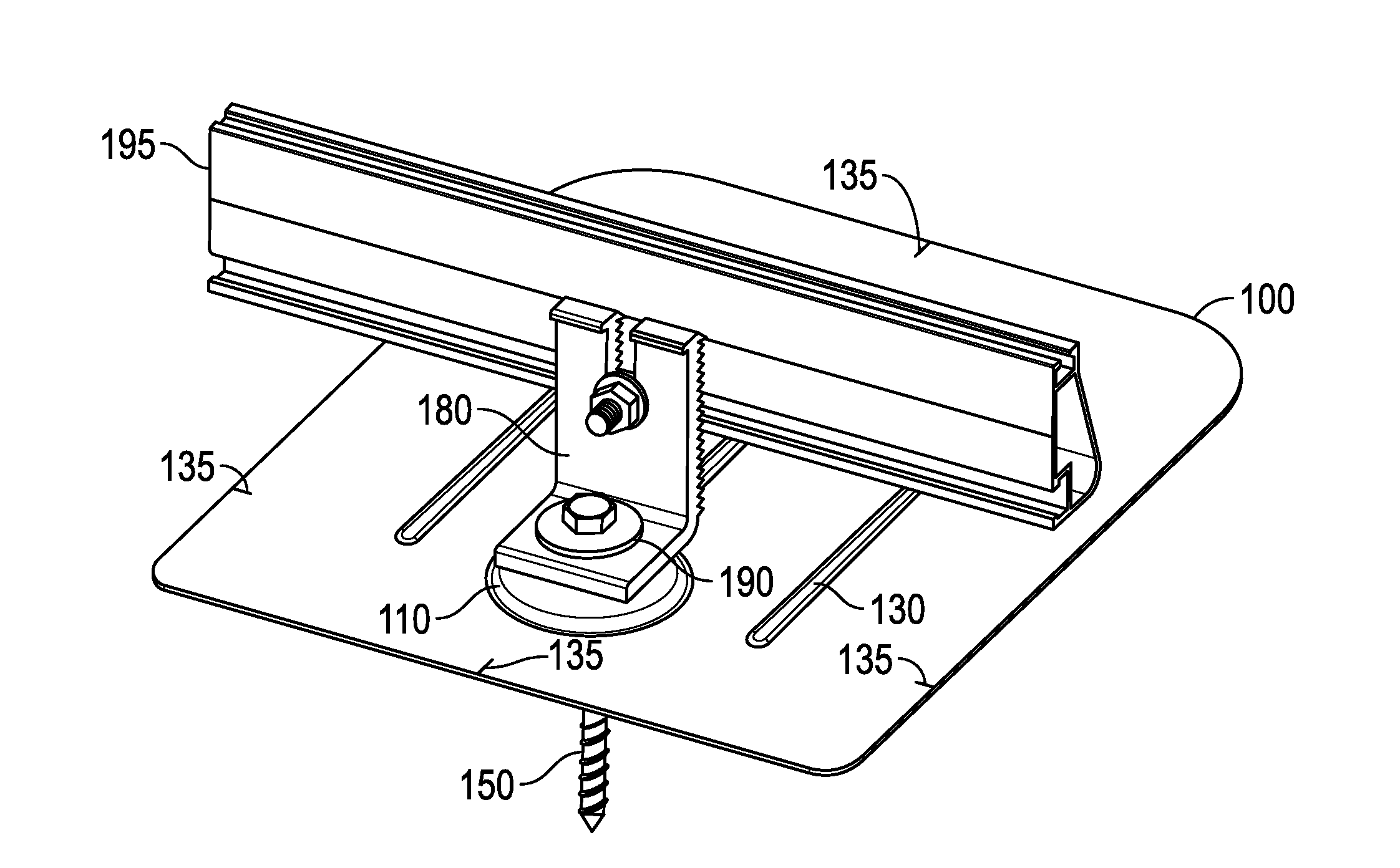
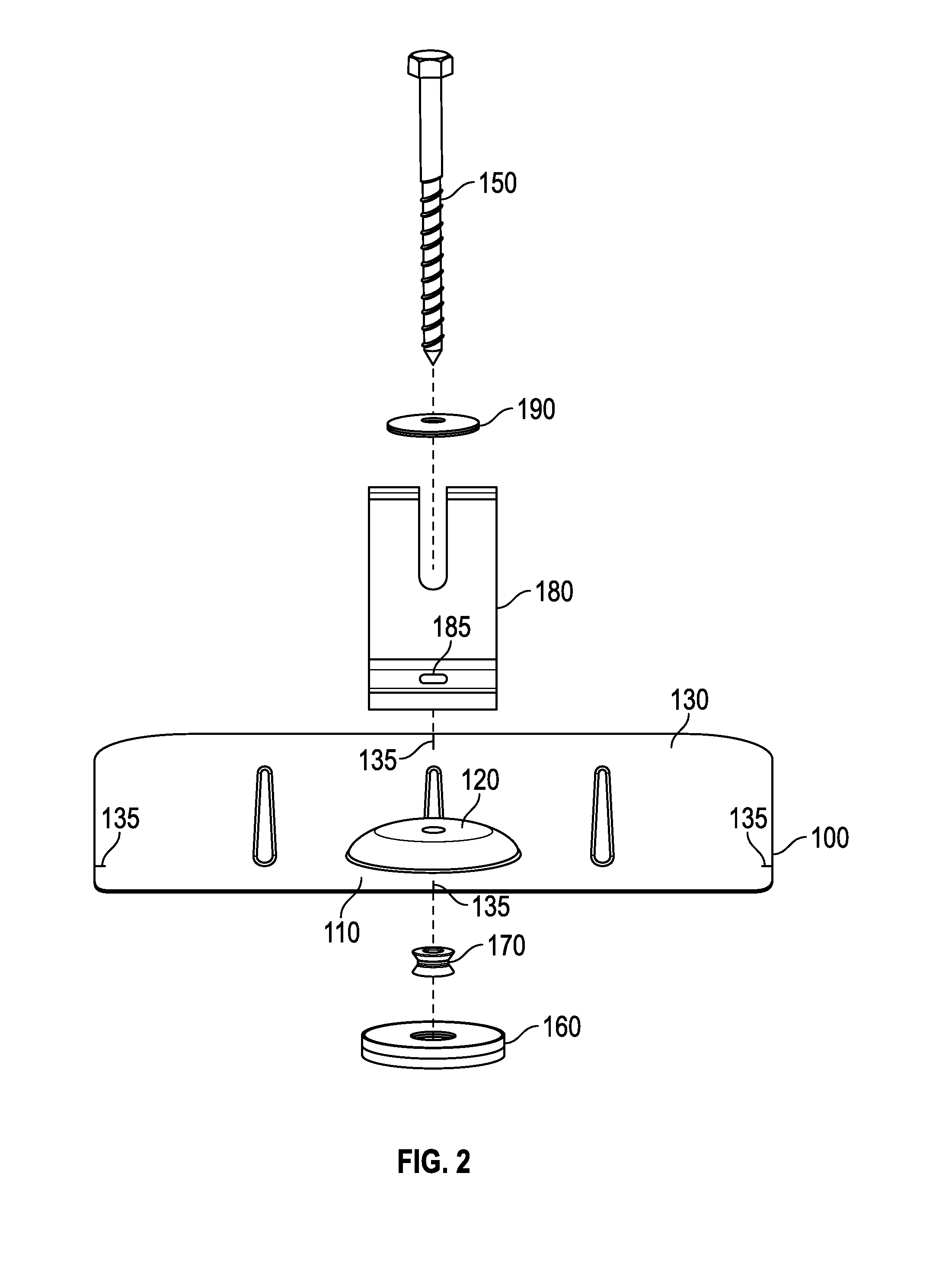
[0034]FIG. 1 illustrates an embodiment of the flashing assembly that is used to secure solar panel mounting rails in a solar panel array on a typical composition shingle roof. The flashing assembly includes a flashing 100. The flashing 100 is generally flat and rectangular, although alternate dimensions can be used as well. The flashing 100 includes a raised portion 110, which is completely hollow inside, and an opening 120 preferably located in the center of the raised portion 110 for use in receiving a fastener 150. The flashing 100 also may include ribs 130, and alignment markings 135 on the upper surface of the flashing 100 that enable accurate installation and location of the flashing 100 on the roof. The fastener 150 shown is a wood screw that is capable of penetrating shingle roofs and securing itself to the rafters below the surface of the roof, although any suitable fastener can be used.

[0035]The assembly also includes a disk, also referred to as a shell, 160 with an openin...


PUM


Abstract

The present invention relates to a novel and improved roof flashing assembly for use in supporting hardware needed to install solar panel arrays on shingle roofs. The assembly is both easy to install and provides an improved watertight seal at the location where the assembly is secured to the rafters of the roof over the state of the art.

Description

BACKGROUND OF INVENTION[0001]The present invention relates generally to a novel and improved roof flashing assembly that is both easy to install and provides a watertight seal to a composition shingle roof structure. One exemplary application of the flashing assembly is to connect it to hardware used to support guide rails that in turn support solar panel arrays installed on these roof structures. More specifically, the invention relates to a flashing assembly that provides improved and stronger watertight seals over the existing prior art flashing assemblies that also provide stronger support for heavy loads from the solar panel array elements that rest on the flashing assemblies.[0002]Existing prior art flashing assembly designs are either unsatisfying in providing an adequate seal to prevent water from seeping into holes created while securing the flashing to the roof, are too complicated to install, or require too many individual parts making them more expensive to manufacture. ...

Claims


Application Information

Patent Timeline
IPC IPC(8): H02S20/23
CPCH02S20/23F24S25/61F24S2025/021Y02B10/10Y02B10/20Y02E10/47Y02E10/50
Inventor MEINE, SHAWNASH, JONLESTER, BRYANTAGGART, DAVID
Owner IRONRIDGE
Why Eureka
Try Eureka