I/O module

a technology of input/output module and module, which is applied in the field of input/output (i/o) modules, can solve the problems of increasing the cost of the controller b>100/b>, increasing the cost and the mount area, and reducing the output precision, so as to save the cost of the controller and minimize the control system. the effect of cost saving

Active Publication Date: 2016-05-12
YOKOGAWA ELECTRIC CORP
View PDF0 Cites 2 Cited by
  • Summary
  • Abstract
  • Description
  • Claims
  • Application Information

AI Technical Summary

Benefits of technology

[0034]By the above configurations, it is possible to implement the I / O module capable of miniaturizing the control system and saving the cost thereof without adversely affecting the output precision and the like.

Problems solved by technology

Therefore, the cost of the controller 100 increases and a mount area of a circuit component increases.
Also, it is necessary to separately provide the current source 312 that is to be used at the analog output (AO) mode and the FET 311 functioning as the switching element that is to be used at the digital output (DO) mode, which also increases the cost and the mount area.
Also, the current source 312 that is to be used at the analog output (AO) mode should be provided with an operational amplifier for each channel so as to keep the output precision of each channel, which also increases the cost and the mount area.
Further, since it is necessary to provide the circuit configuration of FIG. 2 for each channel, the cost and the mount area increase in proportional to the number of channels.
The above factors are obstacles to the miniaturization of the control system that a user desires and thus are not favorable.

Method used


Image

  • I/O module
  • I/O module
  • I/O module

Examples


Embodiment Construction

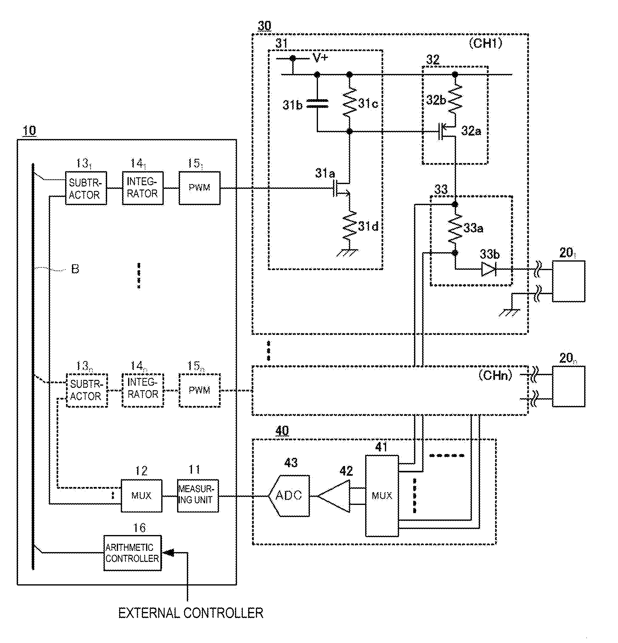
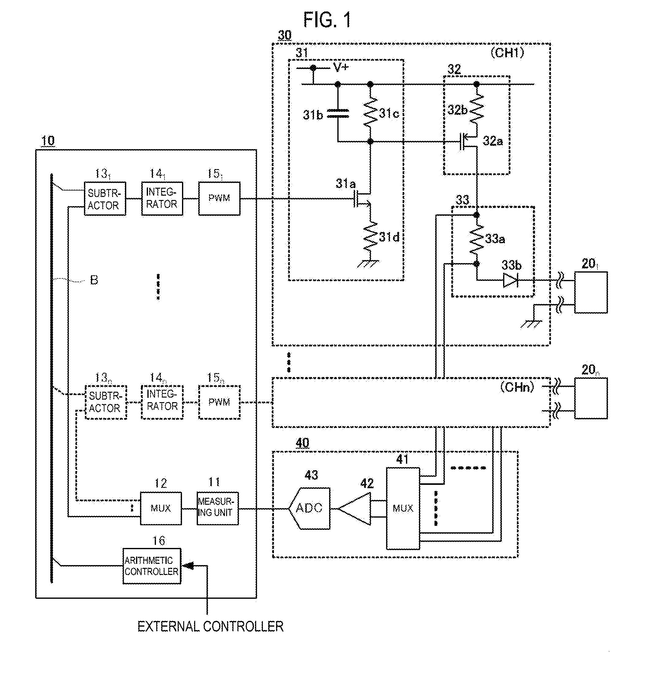
[0037]Hereinafter, an exemplary embodiment of the disclosure will be described in detail with reference to the drawing. FIG. 1 depicts a configuration of an exemplary embodiment of an input / output (I / O) module of the present invention. In FIG. 1, a common controller 10 and field devices 20 of a plurality of n systems are connected to each other via I / 0 modules 30, respectively. The current that is output from each I / O module 30 to each field device 20 is feedback input to the controller 10 via a signal conversion unit 40.

[0038]The controller 10 has a measuring unit 11, a multiplexer 12, a plurality of n measuring systems, an arithmetic controller 16, and the like. The multiplexer 12 is configured to selectively output a measured value of the measuring unit 11 to the predetermined corresponding measuring system. Each measuring system has a subtractor 13, an integrator 14 and a pulse width modulator (hereinafter, referred to as PWM modulator) 15. The arithmetic controller 16 is common...


PUM


Abstract

An input/output (I/O) module is configured to connect a controller and a field device. The I/O module includes a PWM (pulse width modulation) demodulator configured to demodulate a PWM signal that is input from the controller, a current source configured to output a current based on an output signal of the PWM demodulator to the field device, a resistance connected in line with the current source, and a feedback circuit configured to feed back an output current of the current source to the PWM demodulator via the controller.

Description

CROSS-REFERENCE TO RELATED APPLICATION[0001]The present application claims priority from Japanese Patent Application No. 2014-229745 filed on Nov. 12, 2014, the entire content of which is incorporated herein by reference.BACKGROUND[0002]1. Technical Field[0003]The present disclosure related to an input / output (I / O) module, and more specifically, to the I / O module configured to connect a controller, which configures a variety of control systems of a power plant, a manufacturing process, water and sewerage, urban gas and the like, and a field device provided at an outside of the control system.[0004]2. Related Art[0005]FIG. 2 is a block diagram for one channel, which depicts a connection example of a field device in a control system of the related art. In FIG. 2, a controller 100 and a field device 200 are connected via an interface circuit 300.[0006]The interface circuit 300 has a signal unit 310 and an output unit 320.[0007]The signal unit 310 has a FET (field effect transistor) 311...

Claims


Application Information

Patent Timeline
Patent Type & Authority Applications(United States)
IPC IPC(8): H03K9/08
CPCH03K9/08G05B19/0423
Inventor HAYASHI, SHUNSUKETAMBA, MAMORUARIMIZU, TAKESHI
Owner YOKOGAWA ELECTRIC CORP
Why Eureka
Try Eureka