Engine system having coolant control valve

a technology of coolant control valve and engine, which is applied in the direction of machines/engines, mechanical equipment, and non-fuel substance addition to fuel, etc., can solve the problems of deterioration in exhaust gas quality, increase in fuel consumption, and long time taken, so as to improve valve durability, improve temperature control, and improve the effect of cavitation

Active Publication Date: 2016-05-19
HYUNDAI MOTOR CO LTD
View PDF3 Cites 20 Cited by
  • Summary
  • Abstract
  • Description
  • Claims
  • Application Information

AI Technical Summary

Benefits of technology

[0012]Various aspects of the present invention are directed to providing an engine system having a coolant control valve which is beneficial in coping with changes in coolan

Problems solved by technology

With thick oil, friction and fuel consumption increase, and exhaust gas temperatures rise gradually, lengthening the time taken for catalyst activation and causing deterioration in exhaust gas quality.
Moreover, it takes a long time to get a heater to function normally, so passengers and a driver will feel cold.
When the engine coolant temperature is excessively high, knocking may occur.
If ignition timing is adjusted to suppress knocking,

Method used


Image

  • Engine system having coolant control valve
  • Engine system having coolant control valve
  • Engine system having coolant control valve

Examples


Embodiment Construction

[0033]Reference will now be made in detail to various embodiments of the present invention(s), examples of which are illustrated in the accompanying drawings and described below. While the invention(s) will be described in conjunction with exemplary embodiments, it will be understood that the present description is not intended to limit the invention(s) to those exemplary embodiments. On the contrary, the invention(s) is / are intended to cover not only the exemplary embodiments, but also various alternatives, modifications, equivalents and other embodiments, which may be included within the spirit and scope of the invention as defined by the appended claims.

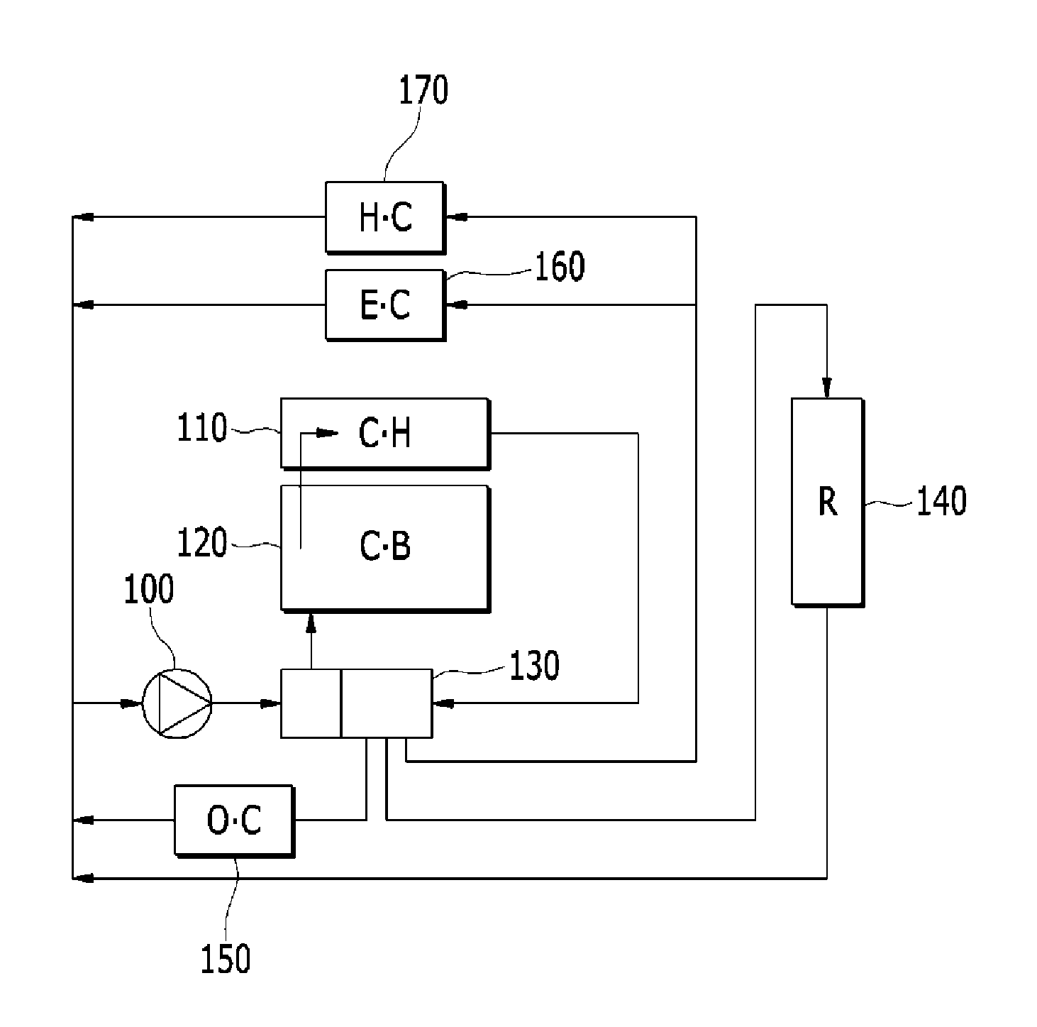
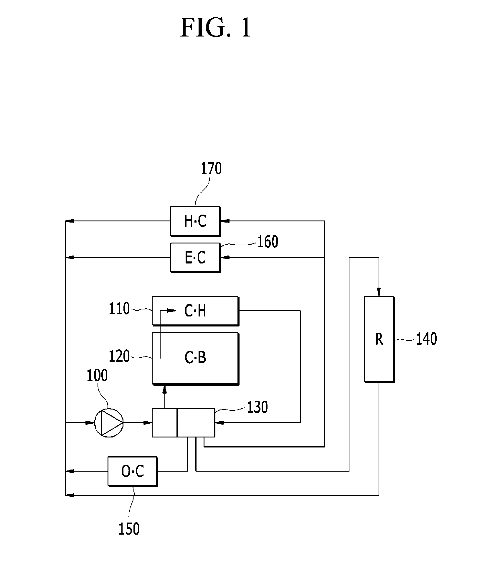
[0034]FIG. 1 is a flowchart showing an overall flow of coolant in an engine system having a coolant control valve according to various embodiments of the present invention.

[0035]Referring to FIG. 1, an engine system includes a cylinder head 110, a cylinder block 120, a coolant control valve 130, a coolant pump 100, an oil cooler 1...


PUM


Abstract

An engine system having a coolant control valve may include a cylinder block configured with cylinders, a cylinder head sitting on top of the cylinder block and comprising exhaust ports and intake ports configured to lead to the cylinders, an Exhaust Gas Recirculation (EGR) cooler, a heater core, an oil cooler, or a radiator through which coolant circulates, and a coolant control valve configured to control a coolant supplied to the cylinder block, a coolant discharged from the cylinder block through the cylinder head, and a coolant supplied to the EGR cooler, the heater core, the oil cooler, or the radiator.

Description

CROSS-REFERENCE TO RELATED APPLICATION[0001]The present application claims priority to Korean Patent Application No. 10-2014-0160899 filed Nov. 18, 2014, the entire contents of which is incorporated herein for all purposes by this reference.BACKGROUND OF THE INVENTION[0002]1. Field of the Invention[0003]The present invention relates to an engine system having a coolant control valve that can improve overall cooling efficiency and reduce fuel consumption by controlling both a coolant supplied to a cylinder block and a coolant discharged from a cylinder head.[0004]2. Description of Related Art[0005]Engines produce torque by burning a fuel to create engine, and discharge surplus thermal energy. Particularly, a coolant absorbs thermal energy as it circulates through an engine, a heater, and a radiator, and releases the thermal energy.[0006]Oil becomes highly viscous at low engine coolant temperatures. With thick oil, friction and fuel consumption increase, and exhaust gas temperatures r...

Claims


Application Information

Patent Timeline
IPC IPC(8): F02M26/22F02F7/00
CPCF02F7/007F02M26/22F01P7/165F01P2003/027F01P2060/04F01P2060/08F01P2060/16F02M26/23F01P3/02F01P2007/146
Inventor LEE, HYO JO
Owner HYUNDAI MOTOR CO LTD
Why Eureka
Try Eureka