
Fuel cell system and method of recoverying cell voltage thereof

a fuel cell and cell voltage technology, applied in the field of recovery control, can solve the problems of easy air flow, drop of cell voltage, etc., and achieve the effects of low pressure loss, high pressure loss, and difficult to effectively discharge water

Inactive Publication Date: 2016-05-19
TOYOTA JIDOSHA KK
View PDF2 Cites 3 Cited by
  • Summary
  • Abstract
  • Description
  • Claims
  • Application Information

AI Technical Summary

Benefits of technology

The patent aims to provide a cell voltage recovery system that reduces water accumulation and pressure loss in a fuel cell system. It achieves this by increasing the flow rate of oxidizing gas and fuel gas during power generation to facilitate water discharge and recover the dropped cell voltage. Additionally, the system synchronizes the flow rate of oxidizing gas with power generation to increase the amount of water discharge. These technical effects improve the efficiency and performance of fuel cell systems.

Problems solved by technology

Excessive accumulation of water in cells constituting a fuel battery causes a drop of cell voltage due to suppression of the supply of reactant gas or the like.
In the case where a water content difference between cells is large, however, it is sometimes difficult to discharge water effectively even by means of the air blow.
Specifically, even if the air blow is performed in a state where a water content difference between stacked cells is large, water is hardly discharged in cells having high water content (in other words, cells requiring the discharge of water, which normally correspond to cells at the ends of the cell stack and cells in the vicinity thereof) due to high pressure loss (consumption of energy such as pressure of a fluid or the energy consumption amount thereof, caused by the shape of a fluid flow path, the smoothness of a surface of the fluid flow path, water accumulating on the fluid flow path and blocking the flow, or the like) and due to difficulty in air flow.
On the other hand, in cells having low water content with low pressure loss, air easily flows and water is excessively discharged.
Therefore, a sufficient discharge effect cannot be achieved only by the aforementioned air blow in a state of a large water content difference, thereby sometimes causing a cell voltage drop again in a short time after the air blow.
Since water is easily discharged, the water excessively accumulated in the cells totally decreases and the dropped cell voltage recovers.
In the fuel battery, the water content of the end cells of the cell stack is apt to be excessive.

Method used


Image

  • Fuel cell system and method of recoverying cell voltage thereof
  • Fuel cell system and method of recoverying cell voltage thereof
  • Fuel cell system and method of recoverying cell voltage thereof

Examples


Embodiment Construction

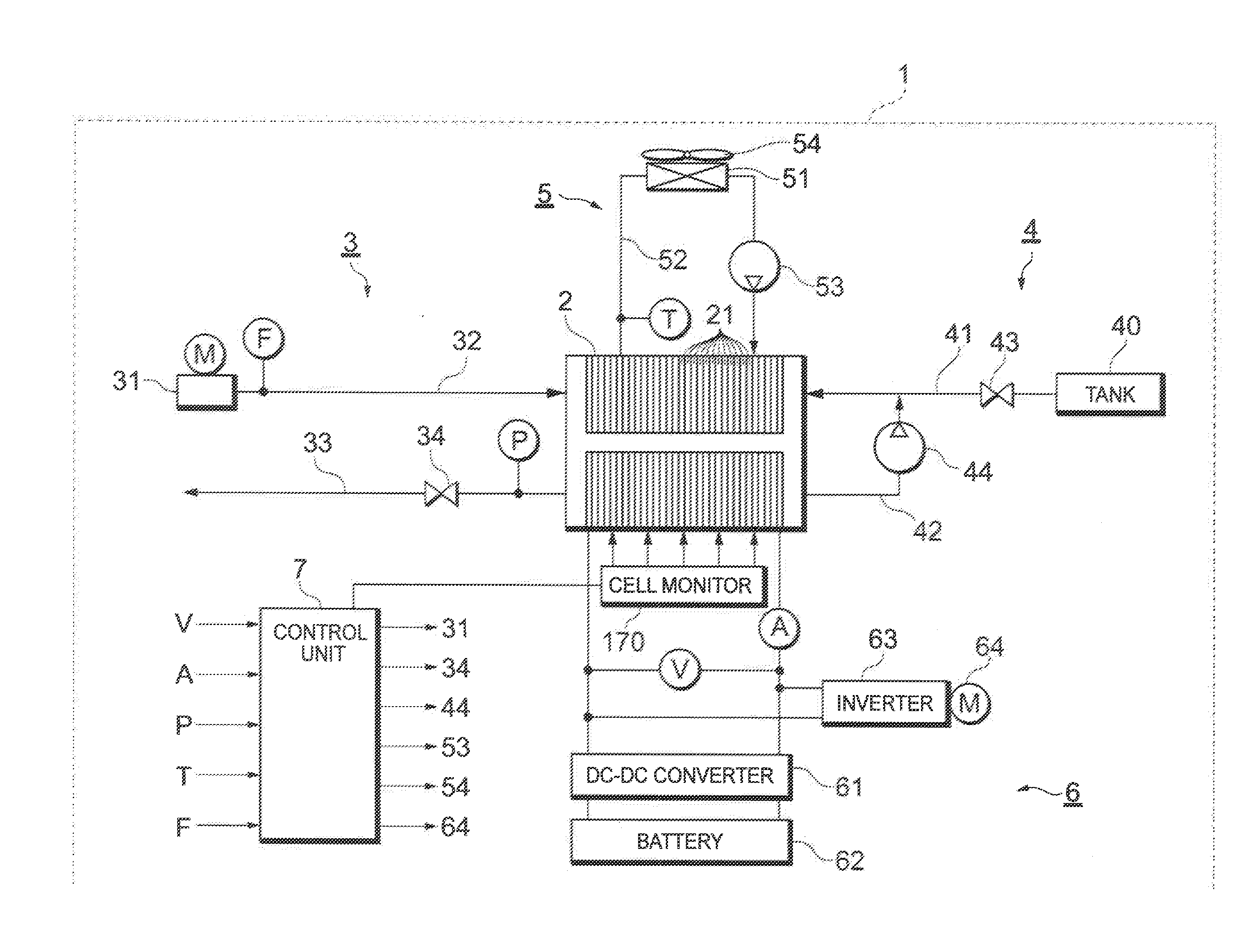
[0030]Hereinafter, preferred embodiments of a fuel cell system according to the present disclosure will be described with reference to the accompanying drawings. In the embodiments described below, description will be made on a case where the fuel cell system is used as an in-vehicle power generation system of a fuel cell hybrid vehicle (FCHV). The fuel cell system according to the present disclosure is also applicable to various mobile bodies (a robot, a vessel, an aircraft, etc.) other than the fuel cell hybrid vehicle and further applicable to a stationary power generation system used as power generation facilities for premises (dwellings, buildings, etc.).

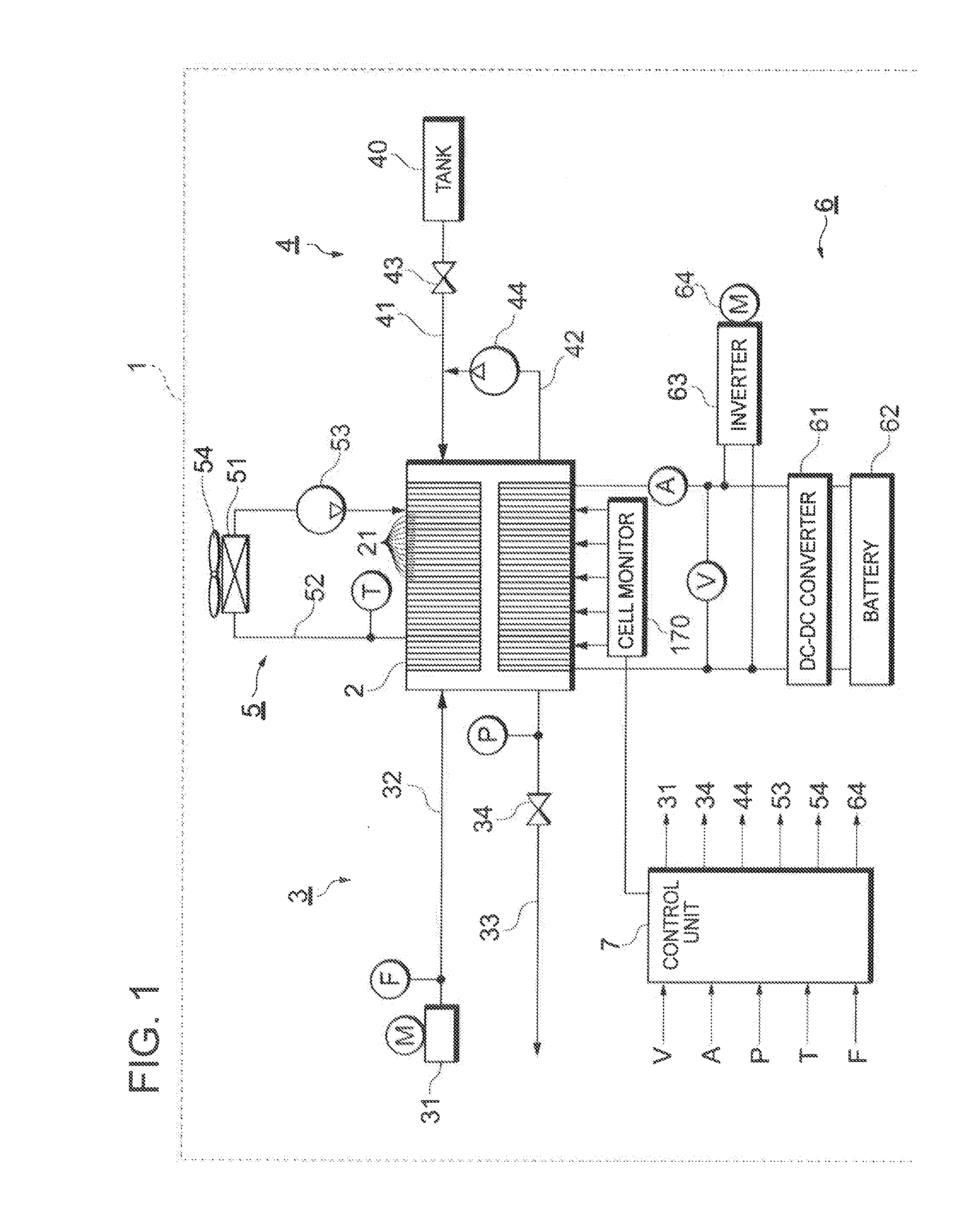
[0031]First, referring to FIG. 1, description will be made on the configuration of a fuel cell system according to this embodiment. FIG. 1 is a configuration diagram schematically illustrating a fuel cell system in this embodiment.

[0032]A fuel cell system 1 has a fuel battery 2 which generates electric power by an electrochemic...


PUM

PropertyMeasurementUnit
cell voltageaaaaaaaaaa
average cell voltage Vaaaaaaaaaaa
cell voltage Vbaaaaaaaaaa

Abstract

An amount of power generation is increased in the case where a difference in water content between some and others of the cells is greater than a predetermined value. In the case of satisfaction of a first condition that the difference in water content between some and others of the cells is greater than the predetermined value, a fuel battery may be caused to perform an operation in which the amount of power generation exceeds that in the normal operation to reduce a cell voltage difference ΔV between an average cell voltage Va and a minimum cell voltage Vb. The first condition is, for example, that the cell voltage difference ΔV, which is a difference between the average cell voltage Va and the minimum cell voltage Vb, is greater than a first threshold value.

Description

BACKGROUND[0001]1. Field[0002]The present disclosure relates to recovery control in the case of a drop of cell voltage in a fuel cell system including a fuel battery composed of a plurality of cells.[0003]2. Background Art[0004]Excessive accumulation of water in cells constituting a fuel battery causes a drop of cell voltage due to suppression of the supply of reactant gas or the like. Therefore, in the case of a drop of the voltage of some of a plurality of cells constituting a fuel battery or in the case where the drop is predicted, water excessively accumulated in the cells is discharged by blowing an oxidizing gas (hereinafter, also referred to as “air blow” in this specification) to stabilize the cell voltage (see, for example, JP2006-294402 A).SUMMARY[0005]In the case where a water content difference between cells is large, however, it is sometimes difficult to discharge water effectively even by means of the air blow. Specifically, even if the air blow is performed in a state...

Claims


Application Information

Patent Timeline
Patent Type & Authority Applications(United States)
IPC IPC(8): H01M8/04H01M8/24
CPCH01M8/04492H01M8/04753H01M2250/20H01M8/24H01M8/04925H01M8/04544H01M8/00H01M8/04H01M8/06H01M8/04552H01M8/0491H01M8/0494Y02E60/50Y02T90/40
Inventor SHIOKAWA, SATOSHIBONO, TETSUYAHAMANOI, OSAMU
Owner TOYOTA JIDOSHA KK
Learn More