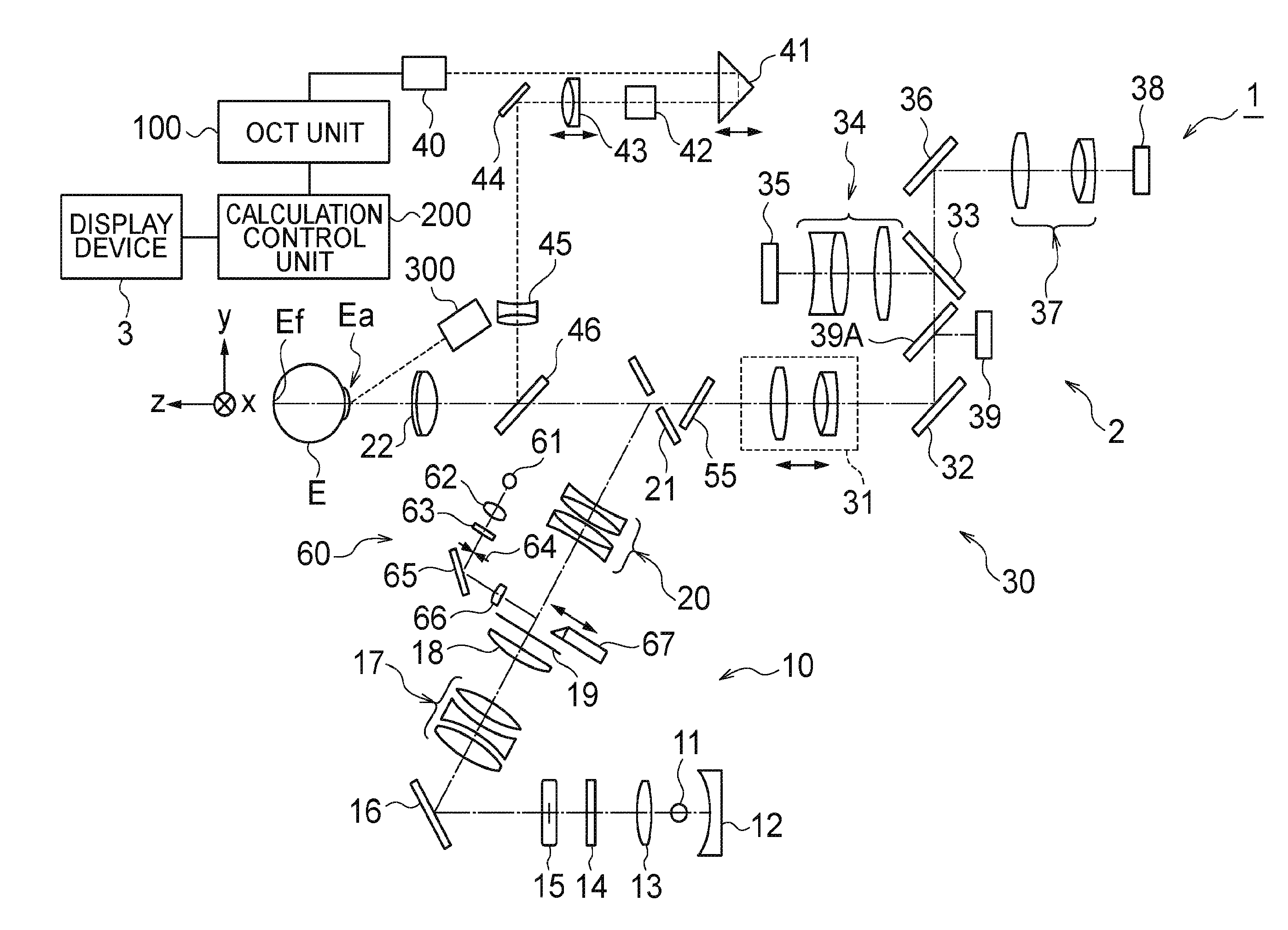
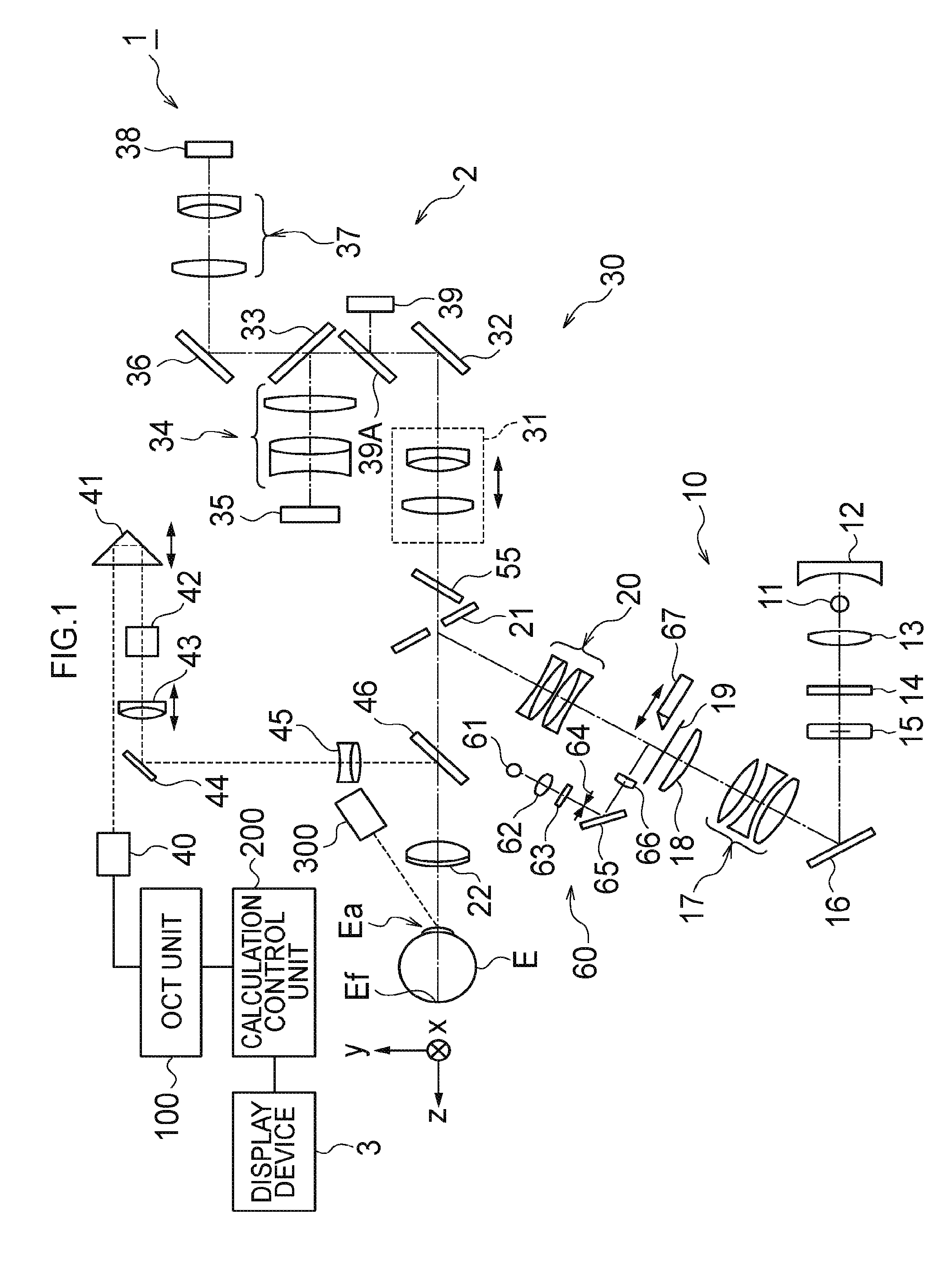
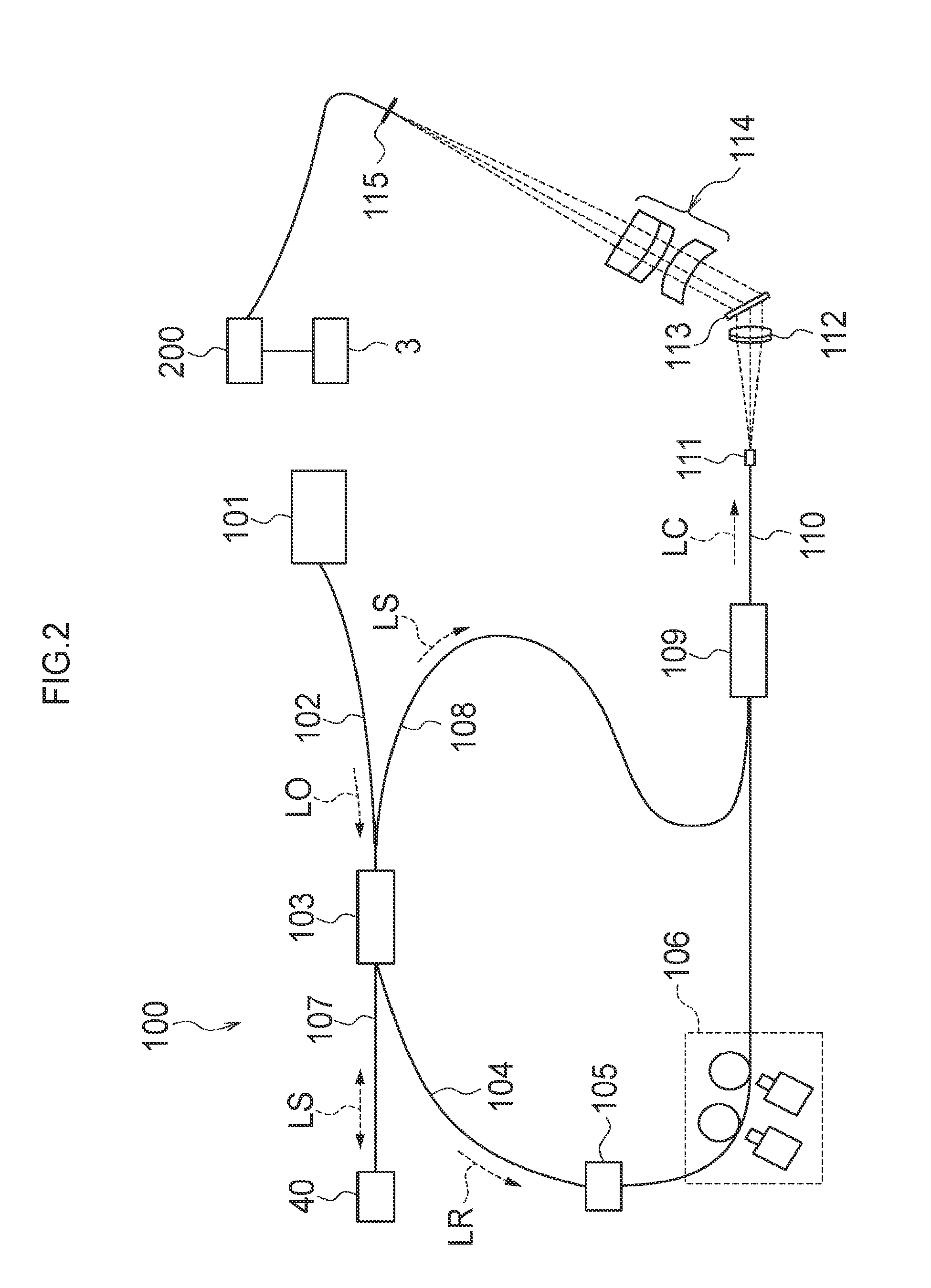
Ophthalmological apparatus
a technology of ophthalmological equipment and ophthalmology, which is applied in the field of ophthalmological equipment, can solve the problems of difficult alignment operation by the other display method, iris blockage of illumination light for the fundus, etc., and achieves the effect of smooth and easy alignment of the optical system, increased size, and low cos
- Summary
- Abstract
- Description
- Claims
- Application Information
AI Technical Summary
Benefits of technology
Problems solved by technology
Method used
Image

Examples
first example
[0205]With reference to FIGS. 12A and 12B, an example of another display mode (first example) will be described. FIGS. 12A and 12B show an example of display screens in cases of forward and backward positional displacement (alignment displacement) of the optical system for inspection with respect to the subject's eye E in the z-direction, respectively, as the example of another display mode (first example). In the present specification, a direction toward a subject side is indicated as a forward direction, and an opposite direction is indicated as a backward direction.
[0206]In the first display mode in the embodiment described above (the same applies to the second display mode), if two alignment index images are displayed in the same display mode, it is difficult to grasp a direction of positional displacement in the z-direction from a positional relationship between the two pseudo alignment index images.
[0207]In contrast, the first example is configured to enable a direction of pos...
second example
[0216]With reference to FIGS. 16A and 16B, an example of another display mode (second example) will be described. FIGS. 16A and 16B show an example of display screens in cases of frontward and rearward positional displacement of the optical system for inspection with respect to the subject's eye E in the z-direction, respectively, as the example of another display mode (second example).
[0217]In the second example, as shown in FIG. 16A, if the positional displacement in the z-direction is in the forward direction, the control unit 210 allows the two pseudo alignment index images 310A and 310B to be displayed in a first color (shown by a solid circle). On the other hand, as shown in FIG. 16B, if the positional displacement in the z-direction is in the backward direction, the control unit 210 allows the two pseudo alignment index images 310A and 310B to be displayed in a second color (shown by an open circle) different from the first color.
[0218]In this way, in the second example, as w...
third example
[0220]With reference to FIGS. 17A and 17B, an example of another display mode (third example) will be described. FIGS. 17A and 17B show an example of display screens in cases where positional displacement of the optical system for inspection with respect to the subject's eye E in the z-direction is in the forward direction, and where a position in the z-direction is proper, respectively, as the example of another display mode (third example).
[0221]In the third example, as shown in FIGS. 17A and 17B, while the two alignment index images 310 and 310 are displayed in the same display form as that of the first display mode in the embodiment described above, an indicator 312 is displayed on the right side of the display screen 308. The indicator 312 serves as an identification device that shows whether positional displacement in the z-direction of the optical system for inspection with respect to the subject's eye E is in the forward direction or the backward direction. Thus, it is possi...
PUM
 Abstract
Description
Claims
Application Information
 - R&D
- Intellectual Property
- Life Sciences
- Materials
- Tech Scout
- Unparalleled Data Quality
- Higher Quality Content
- 60% Fewer Hallucinations
Browse by: Latest US Patents, China's latest patents, Technical Efficacy Thesaurus, Application Domain, Technology Topic, Popular Technical Reports.
© 2025 PatSnap. All rights reserved.Legal|Privacy policy|Modern Slavery Act Transparency Statement|Sitemap|About US| Contact US: help@patsnap.com