Robotic pool cleaning apparatus

a robotic and pool technology, applied in the direction of gymnasiums, buildings, buildings, etc., can solve the problems of obstructing the cleaning unit, tangled hoses used with older units, and few, if any, can clean the surface of the swimming pool cordlessly and autonomously

Active Publication Date: 2016-05-26
FLUIDRA
View PDF0 Cites 64 Cited by
  • Summary
  • Abstract
  • Description
  • Claims
  • Application Information

AI Technical Summary

Benefits of technology

[0012]An object of the present invention is to provide a robotic, autonomous and cordless apparatus that cleans swimming pool surfaces on its own, and that comprises multiple road and pulley wheels on each side of an apparatus frame, each defining a belt path, with a traction belt extending around each belt path. A drive motor rotates a pulley wheel on each side to move the belt and thereby move the apparatus along a swimming pool surface to be cleaned. Driven outside wheels, each with outer friction surfaces to engage the pool surface for also moving the frame, are connected at upper and lower, and forward and rearward sides of each belt path. These outside wheels help turn the apparatus away from side walls if a programmed cleaning path for the apparatus seeks to maintain the apparatus on a floor of the pool, and helps turn the apparatus to move up a side wall and to climb steps or stairs of a pool, for cleaning these surfaces as well.

Problems solved by technology

Few, if any, can clean swimming pool surfaces cordlessly and autonomously, especially in larger pools and irregularly shaped pools.
The tethering cables required for nearly all prior submersible robotic pool cleaners, including all cleaners of comparable performance, can cause problems as the unit moves through the pool.
The cables and hoses used with older units can become tangled and knotted, can become looped over obstacles inside or outside the pool, can physically obstruct the cleaning unit, and otherwise limit proper movement.
Cables also limit the range of the prior art devices, and their out-of-water portions are an unsightly tripping hazard.
The movement and turning of the cleaner over a prolonged period of time can cause the pool cord extending to the surface to become tightly coiled and / or twisted to such an extent that it interferes with the movement of the cleaner, which can pull the cleaner off of its programmed cleaning course.
If a tethered unit has its connection cut or unplugged, the unit is typically rendered inoperable with no convenient way to return it to the surface from the bottom of the pool.
Prior art robotic pool cleaners frequently have a problem with flipping over and getting stuck in that position, particularly if they attempt to clean the sides of pools.
A user returning to check on their pool is likely to find the cleaner “belly up” at the bottom, or flipped sideways and immobile.
This obviously prevents the robot from completing its task, and the user is left guessing at what point the device stopped cleaning.
A problem with the prior art apparatus 900 is that debris can get caught in the joint of pivot pins 904 and 914 to prevent the valve member form closing.
Furthermore, the flow of water in the direction D1, for the open valve, can be impeded because the water has to exert force to keep the valve member 912 open, which may also be jammed closed by excess debris above the member 912.
However, in practice, debris may prevent the flap 902 from completely closing, leaving a partial opening where water and / or debris may escape.
Flaps could also open and leak debris under force of gravity when a pool cleaning robot is tilted at an angle or vertically, such as when cleaning pool walls, especially if there is a lapse in water flow.
Another shortcoming of prior art robotic pool cleaners is that they are poorly adapted to continue forward, such as by pivoting to follow a wall and / or by moving upward, when they encounter a wall or other obstacle.
Notably, wide spin brushes for sweeping debris generally lack sufficient motive power to lift and push a cleaning vehicle upwards.
The above designs are also not well suited for pivoting and continuing forward in the event they hit a wall at an angle, at a side or front corner of the vehicle, because they have little or no motive traction at their corners or on their left and right sides.

Method used


Image

  • Robotic pool cleaning apparatus
  • Robotic pool cleaning apparatus
  • Robotic pool cleaning apparatus

Examples


Embodiment Construction

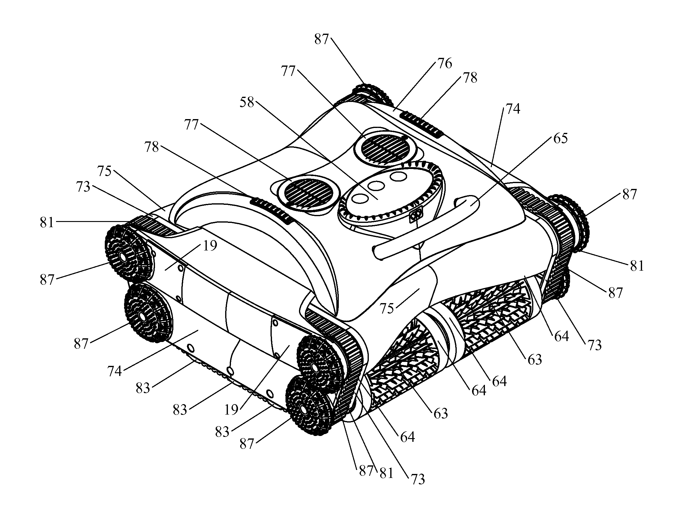
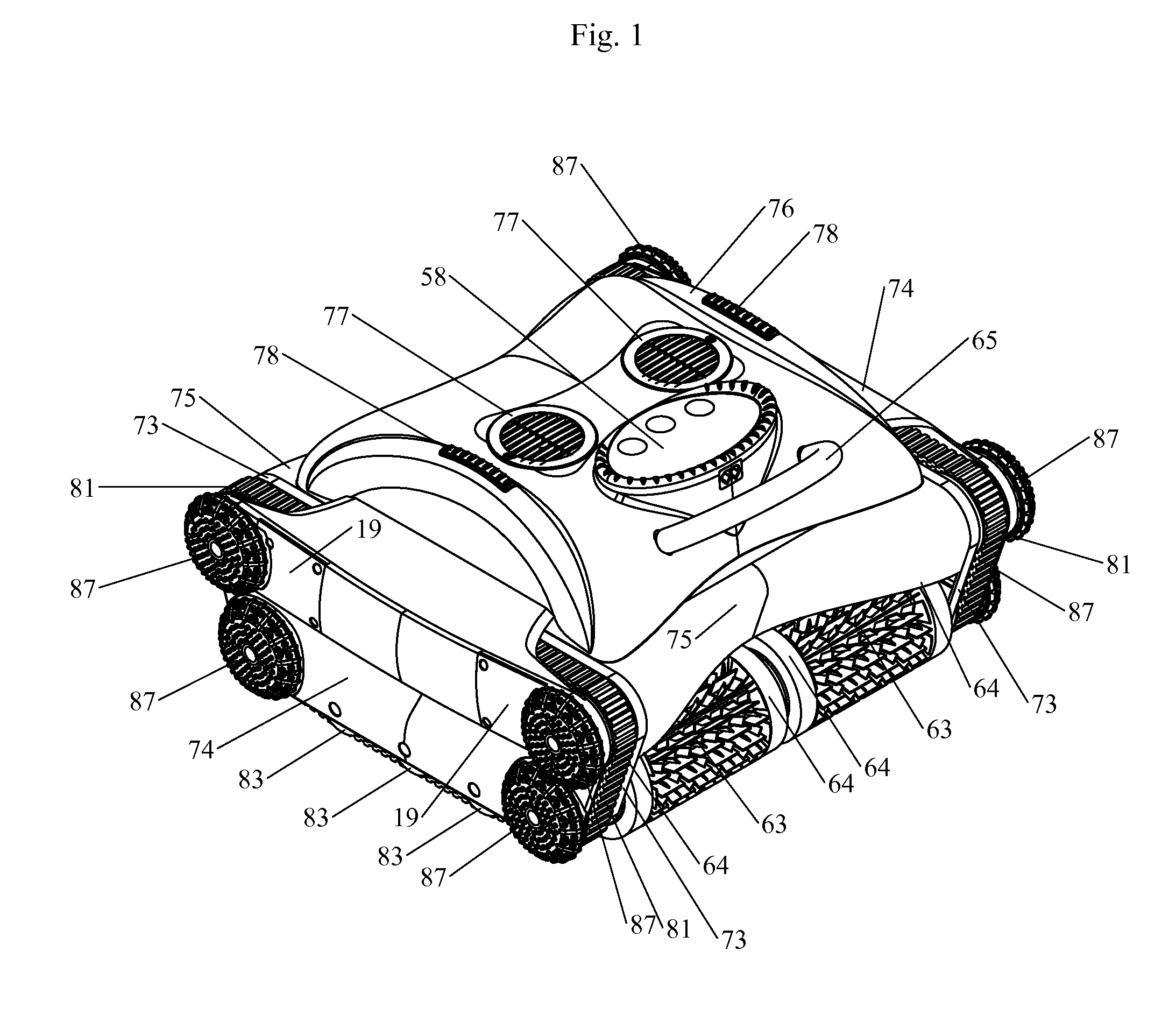
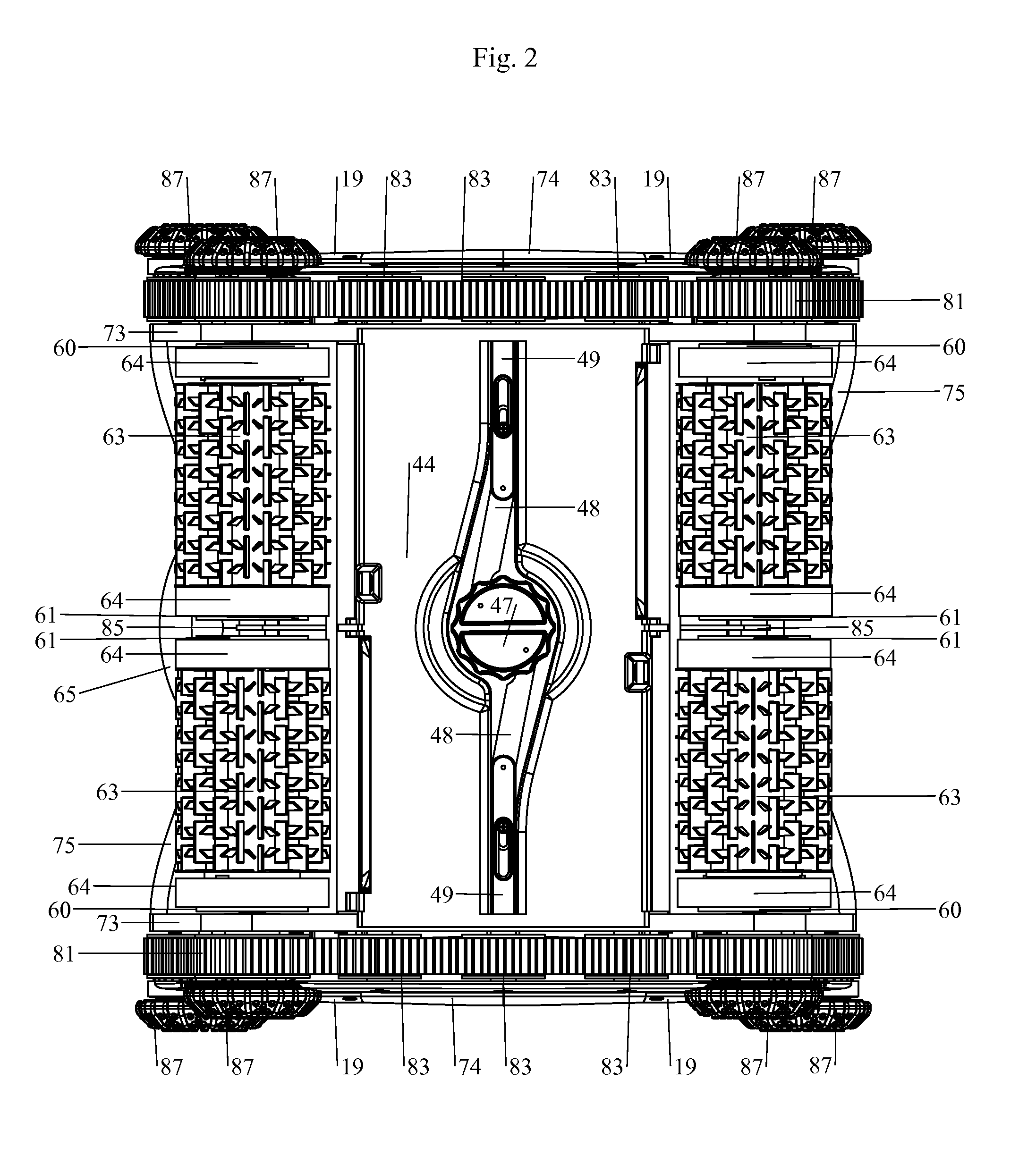
[0100]With reference to FIGS. 1 to 11, a preferred embodiment of a cordless and autonomous robotic apparatus for cleaning surfaces of a swimming pool includes a frame with side frame parts 73 and 73, each with a side frame cover 74. The frame also includes a top cover 76 and front and rear frame body covers 75. The frame has a travel direction axis extending in a forward direction in FIG. 1 that is to the left and angled upwardly, and a rearward direction to the right and angled downwardly. The frame also has a transverse axis that is horizontally perpendicular to the travel direction and a vertical axis extending vertically in FIG. 1.

[0101]As best shown in FIGS. 8B and 9A, four pulley wheels 82 and three road wheels 83 are mounted for rotation to each side frame 73 on rotation axes shown in FIG. 14, that are parallel to the transverse axis. The road and pulley wheels define a trapezoidal belt path of each side of the apparatus frame. First and second track or traction belts 81 exte...


PUM


Abstract

Robotic apparatus cleans swimming pools and has road and pulley wheels with belts thereon, on opposite sides and drive motors that rotate a wheel on each side to move the frame along a pool surface. Pairs of outside wheels have friction surfaces to engage pool surfaces to also moving the frame. Forward and rearward brush assemblies are driven to brush the pool surface. Oppositely facing and angled duck bill valves allow water into free volumes in the frame and are covered by a filter bag for filtering out debris under the action of a dual pump assembly that pumps water out through a pair of outlet opening in a top of the frame. A computer processor controls the drive motors and pump assembly to move the frame along programmed paths and rechargeable batteries power the drive motors, pump assembly and computer processor.

Description

FIELD OF THE INVENTION[0001]This invention relates in general to apparatuses and methods for automatically cleaning swimming pools or other bodies of water with surfaces to be cleaned, and in particular, to a new and useful robotic apparatus for autonomously and cordlessly cleaning swimming pool surfaces. For the purpose of this disclosure, any body of water, including but not limited to swimming pools, pools around fountains, decorative pools or any other body of water that has surfaces in need of periodic or continuous cleaning, will be referred to herein as a swimming pool.BACKGROUND OF THE INVENTION[0002]There are various devices known in the prior art for cleaning swimming pools by crawling along their surfaces. These devices usually use power from the surface, provided by wires, or a flow of water from the surface, provided by a hose, or both. Few, if any, can clean swimming pool surfaces cordlessly and autonomously, especially in larger pools and irregularly shaped pools.[000...

Claims


Application Information

Patent Timeline
Patent Type & Authority Applications(United States)
IPC IPC(8): E04H4/16
CPCE04H4/1654E04H4/1636E04H4/16
Inventor ERLICH, GUYMANY, JOHNEMALEH, JONATHANKOSMYNA, JAMESELLIOTT, CURTISLORYS, THOMASCAMISI, DANIEL
Owner FLUIDRA
Why Eureka
Try Eureka