
Nozzle-type steam trap

a technology of steam traps and nozzles, which is applied in the direction of heating types, separation processes, lighting and heating apparatus, etc., can solve the problems of reducing the productivity of equipment, affecting the quality of products, and affecting the efficiency of equipment, so as to achieve convenient maintenance, easy adjustment and optimization, and easy attachment and removal.

Active Publication Date: 2016-05-26
ECO FIRST
View PDF27 Cites 8 Cited by
  • Summary
  • Abstract
  • Description
  • Claims
  • Application Information

AI Technical Summary

Benefits of technology

The patent text describes a nozzle-type steam trap with a drainage volume adjusting mechanism and a strainer filter. This mechanism allows for easy adjustment and optimization of the amount of drain released, while the strainer filter is easily attached and detached for maintenance. The use of a reinforced screen in the strainer improves the workability of nozzle replacement and filter replacement. These improvements provide a more efficient and effective solution for controlling the discharge of steam and other gases.

Problems solved by technology

If, for example, drain stays in steam-based equipment, the heating efficiency of the equipment degrades, thus significantly decreasing the productivity of the equipment.
In addition, heating unevenness due to drain droplets can be a cause for the quality failure of products and impairs the stable operation of factories.
Yet additionally, drain staying within the vapor transport piping system can be a cause for the occurrence of extremely dangerous steam hammering and may impair the safe operation of factories.
Accordingly, these steam traps suffer severe steam leakage caused by damage to movable portions due to operating delays or repetitive actions and remarkably consume steam.
In addition, the intermittent drainage of a steam trap including a movable portion does not assure the stable operation of steam-based equipment.
Such a method has the problem, however, in which the range of the abovementioned change in the discharged amount of drain that the method can cope with is limited, in spite of the method's high workload.
That is, the abovementioned conventional nozzle-type steam traps have a first problem in which adjustments following a change in the amount of drainage are difficult to make and the range of changes to be coped with is limited.
On the other hand, the abovementioned nozzle-type steam traps have the problem in which since the diameter of a nozzle that drain passes through is small, pipes are liable to become clogged with foreign matter, such as rust or dust.
Rigidity degrades extremely along with the microstructuring of screens, however, thus making it extremely difficult to retain the form of a screen itself and attach / detach and clean the screen.
As described above, the abovementioned nozzle-type steam traps have a second problem in which rigidity degrades along with the miniaturization of screen meshes, thus making it difficult to retain the form of a screen itself and handle the screen for attachment / detachment or cleaning.

Method used


Image

  • Nozzle-type steam trap
  • Nozzle-type steam trap
  • Nozzle-type steam trap

Examples


first embodiment

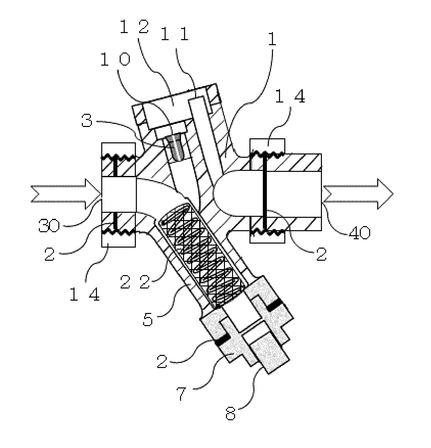
[0049](a) of FIG. 5 is a cross-sectional view of a Venturi nozzle-type steam trap according to the present invention. As is evident from the figure, a drainage volume adjusting component 15 in which the position of a non-drain system vent 11 is continuously variable with respect to a drain vent 10 of a Venturi nozzle 3 is disposed in the steam trap using a union 14. As is evident from the cross-sectional view ((a) of FIG. 5) and the side view ((b) of FIG. 5), this steam trap is fabricated by forming the non-drain system vent 11 inside an cross-sectional area of a drain reservoir 12 and connecting a pipe including the drain reservoir 12 and a pipe provided with the non-drain system vent 11 by means of a union, a flange or the like rotatable on the same axis. Accordingly, the height difference between the drain vent 10 and the non-drain system vent 11 can be controlled freely. It is therefore possible to adjust and optimize the discharged amount of drain for a change in the discharged...

second embodiment

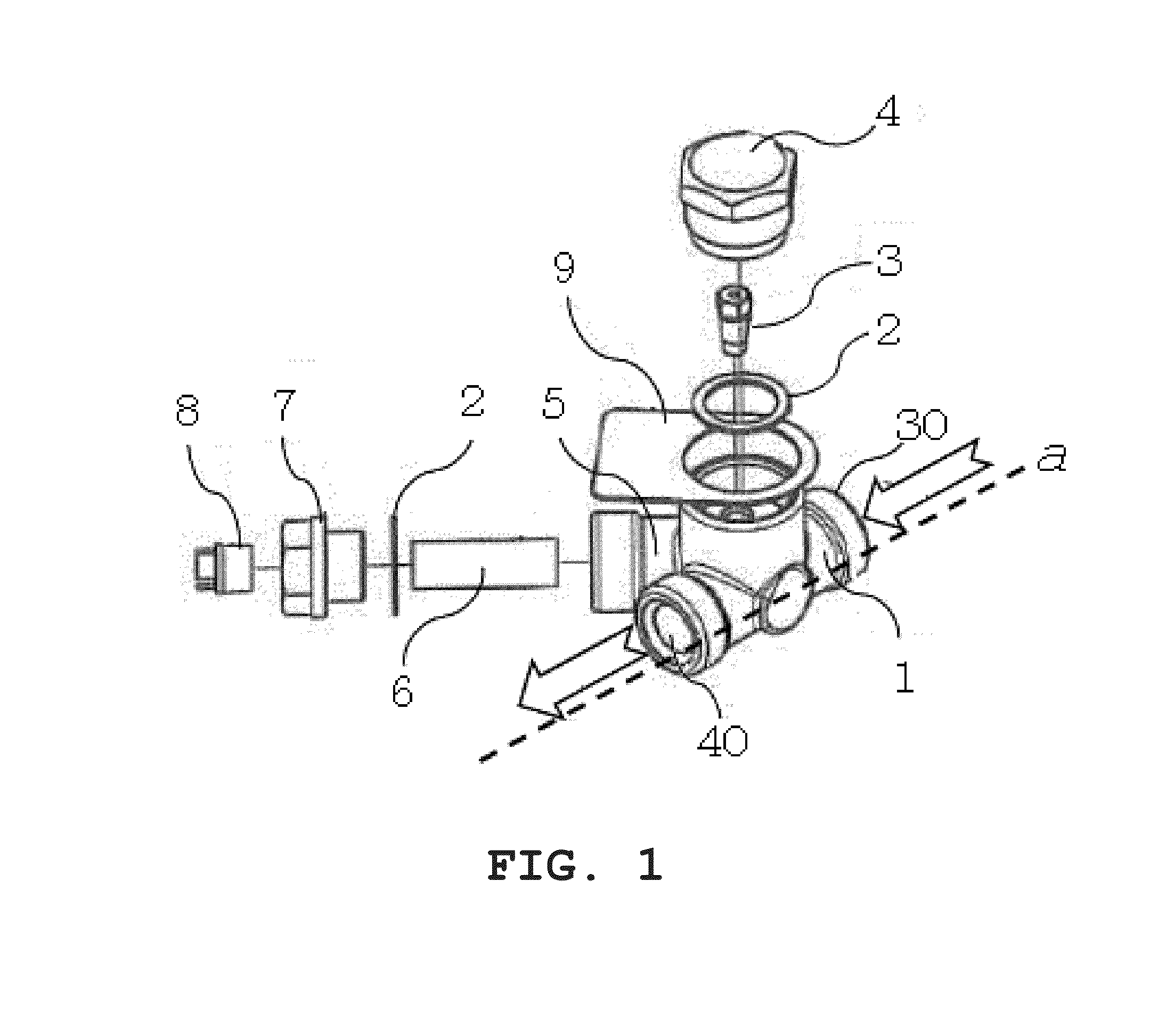
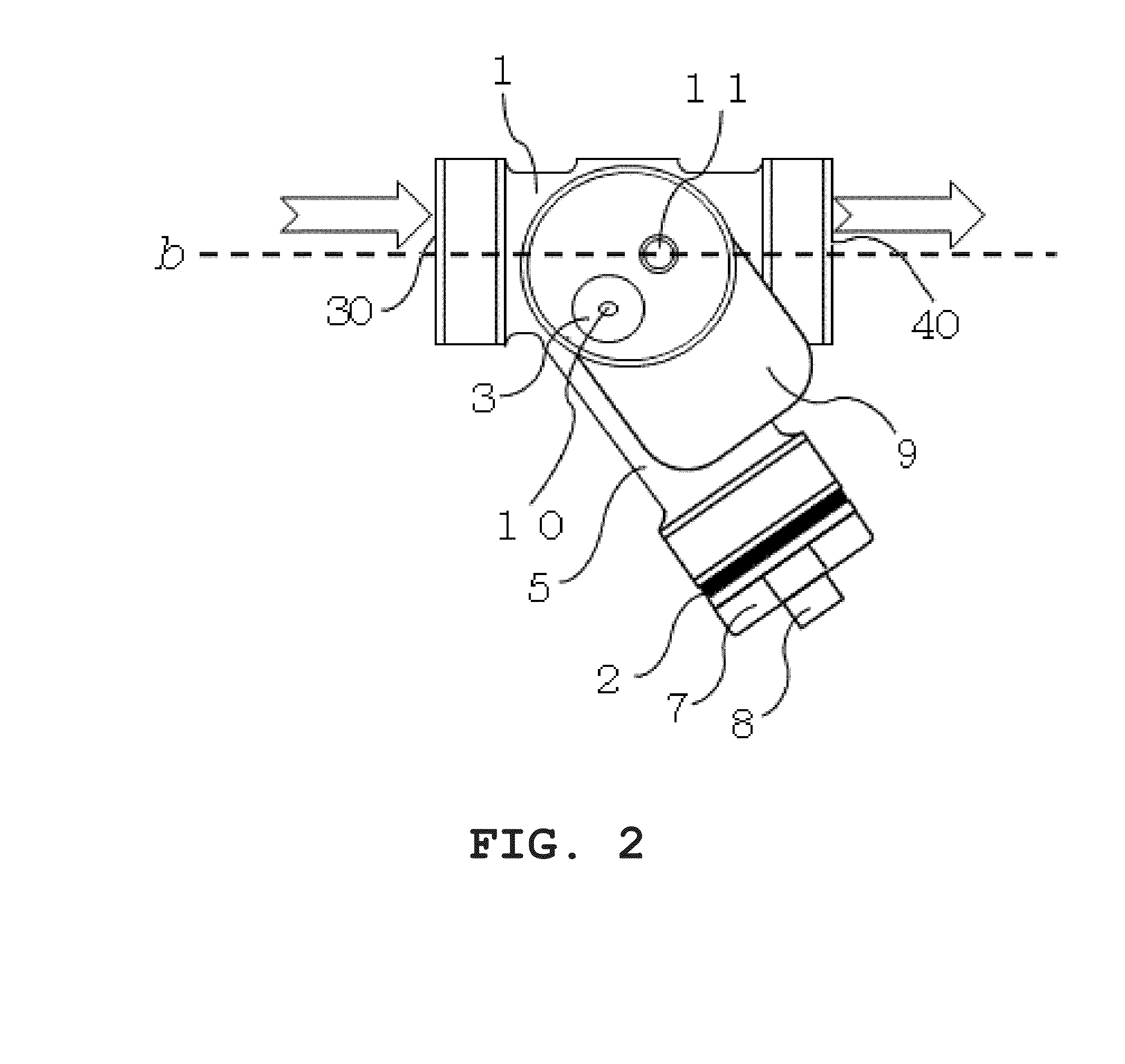
[0050]FIGS. 6 to 9 illustrate a Venturi nozzle-type steam trap according to the present invention. This steam trap is characterized by additionally attaching a drainage volume adjusting component 15 to the conventional Venturi nozzle-type steam trap illustrated in FIG. 2. The drain vents 10 of the Venturi nozzles illustrated in FIGS. 2 and 6 are the same, but the non-drain system vent 11 illustrated in FIG. 2 serves as an intra-drain reservoir conduction port 13 (conventional non-drain system vent 11) for circulating drain throughout the reservoir 12 in FIGS. 6 to 9. In addition, the non-drain system vent 11 illustrated in FIG. 2 is disposed in the drainage volume adjusting component 15 in FIGS. 6 to 9. This drainage volume adjusting component 15 is connected to the body 1 on the same axis using a rotatable union, flange or the like, so that the height difference between the drain vent 10 and the non-drain system vent 11 is continuously variable.

[0051]As is evident, from FIGS. 7 to ...

third embodiment

[0053]FIGS. 10 and 11 illustrate the present invention. This steam trap is characterized by additionally attaching a drainage volume adjusting component 15 in which the non-drain system vent 11 is formed using a partition, in contrast to the drainage volume adjusting component 15 in which such a non-drain system vent 11 as illustrated in FIGS. 8 and 9 is formed as a pass-through slot. This steam trap features a modified shape of the non-drain system vent 11. The non-drain system vent 11 may have any shapes, as long as the vent serves the same function.


PUM

PropertyMeasurementUnit
diametersaaaaaaaaaa
heightaaaaaaaaaa
volumeaaaaaaaaaa

Abstract

An orifice nozzle-type steam trap, a Venturi nozzle-type steam trap, and / or a tunnel-structured resistance tube-type steam trap are provided capable of coping with a change in the discharged amount of a drain due to, for example, a variation in the amount of steam used resulting from the operating condition of steam-based equipment, seasonal external factors and / or a variation in the working pressure difference between the inlet and outlet of a steam trap. A strainer filter can be provided that eliminates strength insufficiency due to the miniaturization of strainer screens of these nozzle-type steam traps, retains the forms of the screens, allows the screens to be easily attached to and detached from the strainers, and / or makes maintenance, such as screen cleaning, easy. The orifice nozzle-type, Venturi nozzle-type, and tunnel-structured resistance tube-type steam traps include, for example, a drainage volume adjusting mechanism which is a piping structure in which the height difference between the drain vent and the non-drain system vent of a Venturi nozzle is variable. In addition, the strainer filter includes, for example, a support body for reinforcing the rigidity of a screen attached to a strainer disposed on the inner side and / or the outer side of the screen.

Description

RELATED APPLICATIONS[0001]This application is a continuation-in-part application of, and claims priority to, International Application No. PCT / JP2014 / 070163 (international publication WO / 2015 / 016298) filed Jul. 31, 2014, which in turn claims priority to Japanese patent application No. JP2014-112882 filed May 30, 2014 and JP2013-161493 filed Aug. 2, 2013. All of the above applications are hereby incorporated herein by reference in their entirety.TECHNICAL FIELD[0002]The present invention relates to nozzle-type steam traps, including Venturi nozzle-type, orifice nozzle-type and / or tunnel-structured resistance tube-type steam traps for automatically and continuously discharging drain (steam condensate resulting from the condensation of steam) arising in steam-based equipment and a vapor transport piping system installed among these equipment out of the system in a variety of facilities, including factories and offices, which use steam as a heat source through a heat exchanger.BACKGROUN...

Claims


Application Information

Patent Timeline
Patent Type & Authority Applications(United States)
IPC IPC(8): F16T1/12
CPCF16T1/12B01D35/02F16T1/34
Inventor KATSURA, TSUTOMU
Owner ECO FIRST
Learn More