

Modular Lighting System
- Summary
- Abstract
- Description
- Claims
- Application Information
AI Technical Summary
Benefits of technology
Problems solved by technology
Method used
Image

Examples
Embodiment Construction
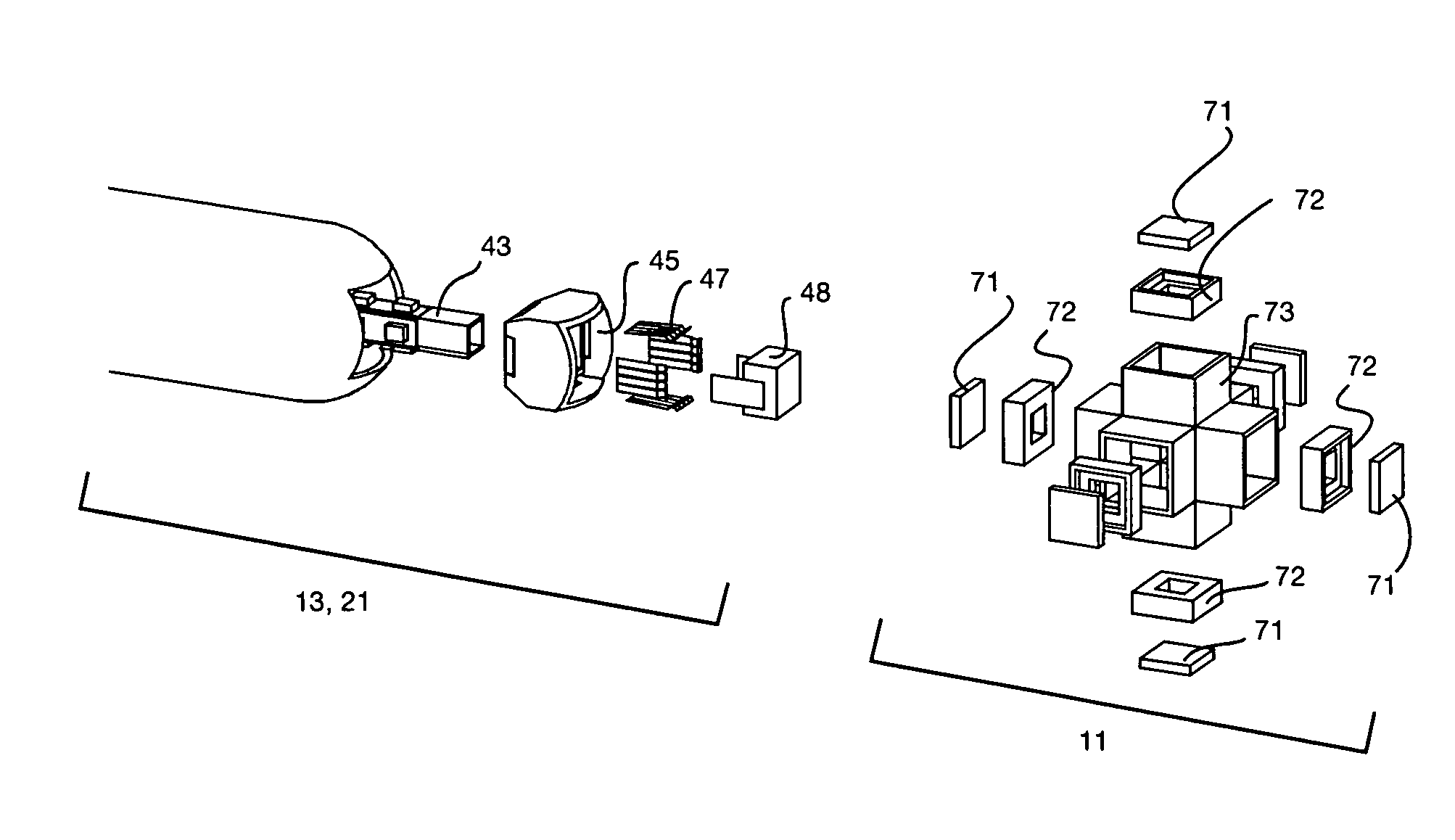
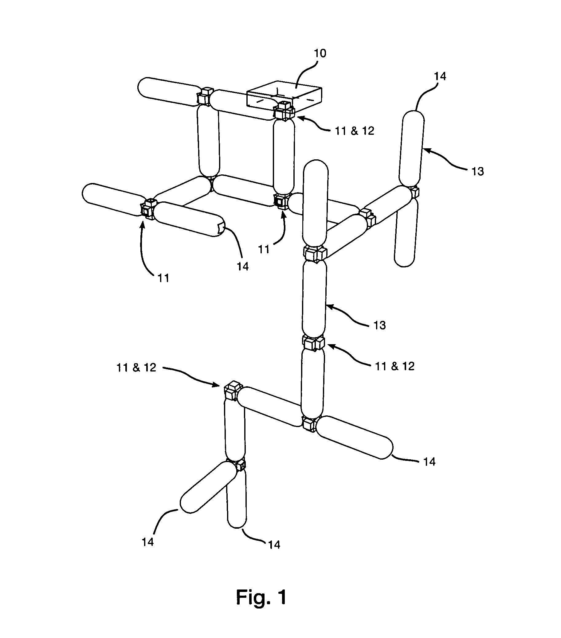
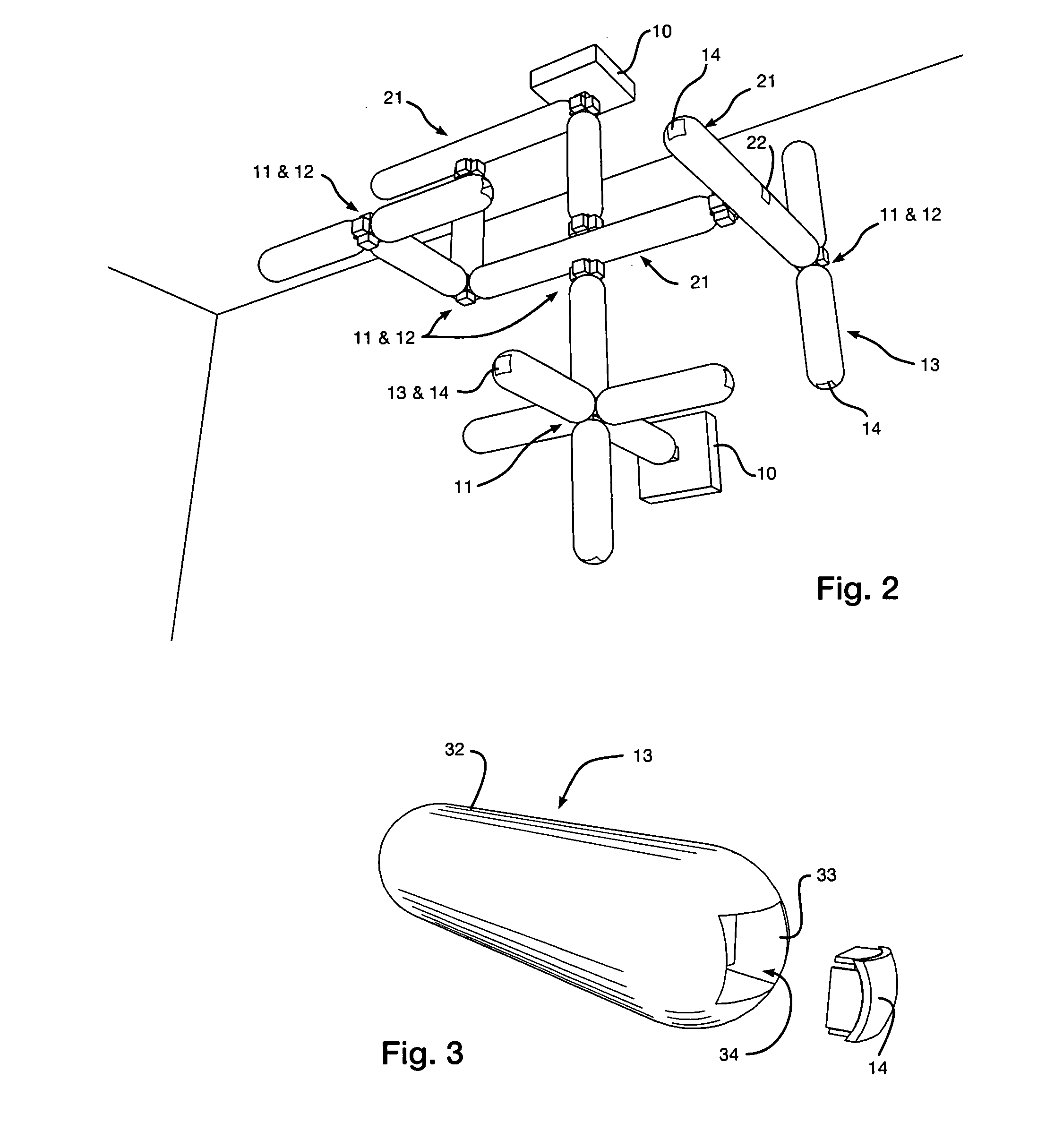
[0006]In a first embodiment of the invention, there is provided an illuminating module containing a light source and mechanical and electrical connectors in a protective light-transmissive shell, and typically includes structural supports, wiring, controlling electronics and thermal dissipation. In this embodiment, the connecting area of the illuminating module mechanically and electrically connects one or more distinct intermediate connectors, to which other similar illuminating modules are connected. The intermediate connectors may be of various shapes to allow for illuminating modules to be connected in various attachment positions and angles, creating variable two and three-dimensional connection patterns, while allowing for thermal conductivity away from the modules.
[0007]In a related embodiment, a similar illuminating module may alternatively include at least one integrated connector within the assembly. In this embodiment, the integrated connector enables each illuminating mo...
PUM
 Abstract
Description
Claims
Application Information