Fuel cell system

Active Publication Date: 2016-05-26
PANASONIC INTELLECTUAL PROPERTY MANAGEMENT CO LTD
View PDF0 Cites 7 Cited by
  • Summary
  • Abstract
  • Description
  • Claims
  • Application Information

AI Technical Summary

Benefits of technology

The patent provides a fuel cell system that improves efficiency and reliability to address common issues. This means that the system works better and is more dependable.

Problems solved by technology

Such sulfur compounds poison a reforming catalyst for reforming the raw material and an electrode catalyst of a fuel cell, and decrease performance of the catalysts.
However, conventional techniques described in above-mentioned Japanese Patent No. 5507119, Japanese Unexamined Patent Application Publication No. 2013-191280, and Japanese Patent No. 5584507 are still susceptible to improvement in view of a quest for further increase in the efficiency and reliability of the fuel cell system.

Method used


Image

  • Fuel cell system
  • Fuel cell system
  • Fuel cell system

Examples


embodiment 1

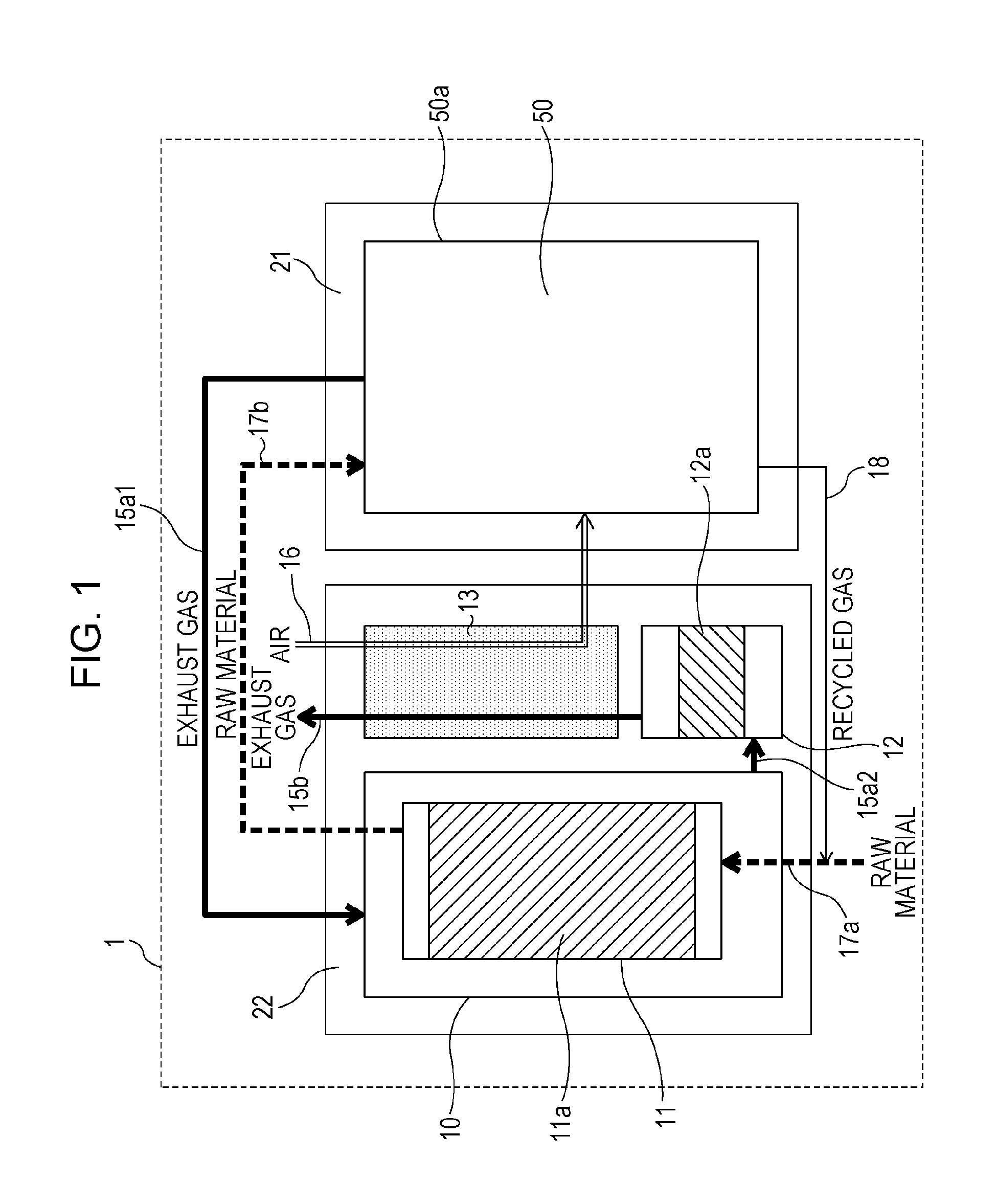
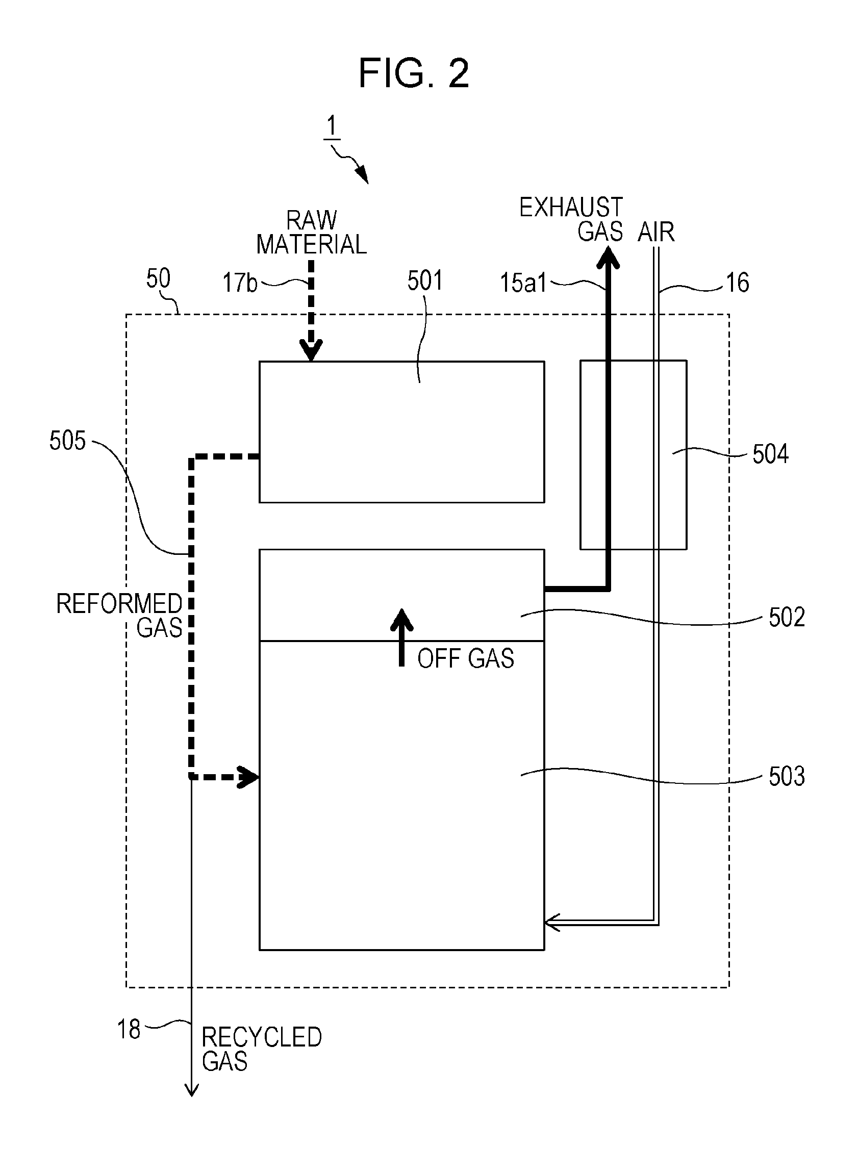
[0042]A structure of a fuel cell system 1 according to Embodiment 1 is described with reference to FIG. 1. FIG. 1 is a block diagram that schematically illustrates an example of the structure of the fuel cell system 1 according to Embodiment 1. The fuel cell system 1 includes a fuel cell unit 50, a desulfurizer 11, a combustion exhaust gas container 10, a purifier 12, and a second air heat exchanger 13.

[0043]The desulfurizer 11 is a reactor that removes a sulfur compound in raw material gas and includes a desulfurization catalyst 11a.

[0044]When a hydrodesulfurization catalyst is used as the desulfurization catalyst, examples of the desulfurization catalyst 11a include a CuZn-based desulfurization catalyst that has both a function of changing a sulfur compound into hydrogen sulfide and a function of adsorbing the hydrogen sulfide. The CuZn-based desulfurization catalyst exerts a desulfurization function in a temperature range of, for example, 100° C. to 400° C., or desirably of 150°...

embodiment 2

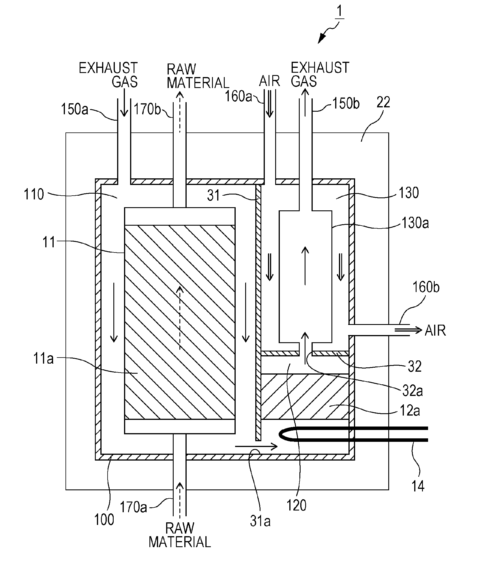
[0093]A structure of a fuel cell system 1 according to Embodiment 2 is described with reference to FIGS. 8 and 9. FIG. 8 is a block diagram that schematically illustrates an example of the structure of the fuel cell system 1 according to Embodiment 2. FIG. 9 is a block diagram that schematically illustrates an example of a structure of a second heat insulator 22 illustrated in FIG. 8 in a second heat insulation space.

[0094]The second heat insulator 22 is provided among the combustion exhaust gas container 10, the purifier 12, and the second air heat exchanger 13 according to Embodiment 1. In Embodiment 1, the combustion exhaust gas container 10, the purifier 12, and the second air heat exchanger 13 are arranged independently in the second heat insulation space of the second heat insulator 22. In contrast, in the fuel cell system 1 according to Embodiment 2, a combustion exhaust gas container 10, a purifier 12, and a second air heat exchanger 13 are arranged in one integral container...


PUM


Abstract

A fuel cell system includes a desulfurizer that removes a sulfur compound in a raw material, a fuel cell unit that performs electric-power generation using fuel obtained by reforming a raw material from which the sulfur compound is removed and electric-power generation air supplied, a combustion exhaust gas passage through which combustion exhaust gas generated by combusting fuel not utilized for the electric-power generation in the fuel cell unit is emitted, a combustion exhaust gas container that is connected to the combustion exhaust gas passage and accommodates the desulfurizer inside the combustion exhaust gas container, a purifier that removes carbon monoxide included in the combustion exhaust gas, and an air heat exchanger that performs heat exchange of the combustion exhaust gas and the electric-power generation air supplied to the fuel cell unit.

Description

BACKGROUND[0001]1. Technical Field[0002]The present disclosure relates to a fuel cell system including a desulfurizer that removes a sulfur compound in a raw material supplied to a fuel cell unit, a purifier that removes carbon monoxide in combustion exhaust gas emitted from the fuel cell unit, and a heat exchanger that performs heat exchange of air supplied to the fuel cell unit and the combustion exhaust gas.[0003]2. Description of the Related Art[0004]Conventionally, a fuel cell system has high efficiency of electric-power generation even when the fuel cell system is small in size. Thus, the fuel cell system is utilized as an electric-power generator in a distributed electric-power generation system. Typical examples of a raw material supplied to the fuel cell system include natural gas (urban gas), liquefied petroleum gas (LPG), gasoline, and kerosene, which are supplied from already-existing infrastructures.[0005]The raw material described above includes, for example, a sulfur ...

Claims


Application Information

Patent Timeline
IPC IPC(8): H01M8/06H01M8/04
CPCH01M8/0675H01M8/0618H01M8/04022H01M8/0668H01M8/04014H01M8/04067H01M8/04701H01M8/04708H01M8/04716H01M8/04738C01B3/38C01B2203/0233C01B2203/066C01B2203/1241C01B2203/1247C01B2203/127Y02P20/129Y02E60/50
Inventor KITA, HIROMIUKAI, KUNIHIROSUKAWA, TORU
Owner PANASONIC INTELLECTUAL PROPERTY MANAGEMENT CO LTD
Why Eureka
Try Eureka