Surgical guidance system

a surgical and guidance system technology, applied in the field of guidance systems, can solve the problems of imposing significant errors and comparatively large errors in calculation, and achieve the effects of improving accuracy and speed of system, facilitating inspection, and speeding up and improving accuracy

Inactive Publication Date: 2016-06-02
ARTHREX
View PDF0 Cites 31 Cited by
  • Summary
  • Abstract
  • Description
  • Claims
  • Application Information

AI Technical Summary

Benefits of technology

[0011]The embodiments are based on the object of providing a guidance system which allows precise aiming and precise drill depth measurement without using an x-ray imaging system. The guidance system should be comparatively compact and easy to handle. The manufacturing and operating costs should be lower than with comparable guidance systems.
[0012]In an embodiment, the system comprises a probe, wherein the probe is preferably utilized for highlighting the end point or a position close to the end point within the patient's body to which the drill bore should extend. As such, the probe preferably has a tip, which may be at the end of a shaft and which may be positioned within a patient's body. Further, the system advantageously comprises a targeter or target module, wherein the targeter is configured to be able to sense the tip of the probe, and thus the end point of a drill line. The system preferably comprises some form of drill guide or drill tube which is included with or integrated into the targeter for providing a guidance to a drill tip when drilling into the patient's body, such that measurements made by the targeter can be used to align the drill guide to the desired end point of the bore to be drilled. The drill guide is defining a drill line. It further may have a reference position for determining the distance of this reference position to the tip of the probe. Preferably, the reference position is at the end and most preferably at the distal end of the drill guide. The tip of the probe may have any shape suitable for pointing to any location or position. It may be a sharp tip, or it may have a ball shape to prevent injuries or damage of tissue.

Problems solved by technology

This calculation bears comparatively large errors, as the known tracking systems are comparatively precise in the measurement of positions, but impose significant errors when determining the orientation of an object in space.

Method used


Image

  • Surgical guidance system
  • Surgical guidance system
  • Surgical guidance system

Examples


Embodiment Construction

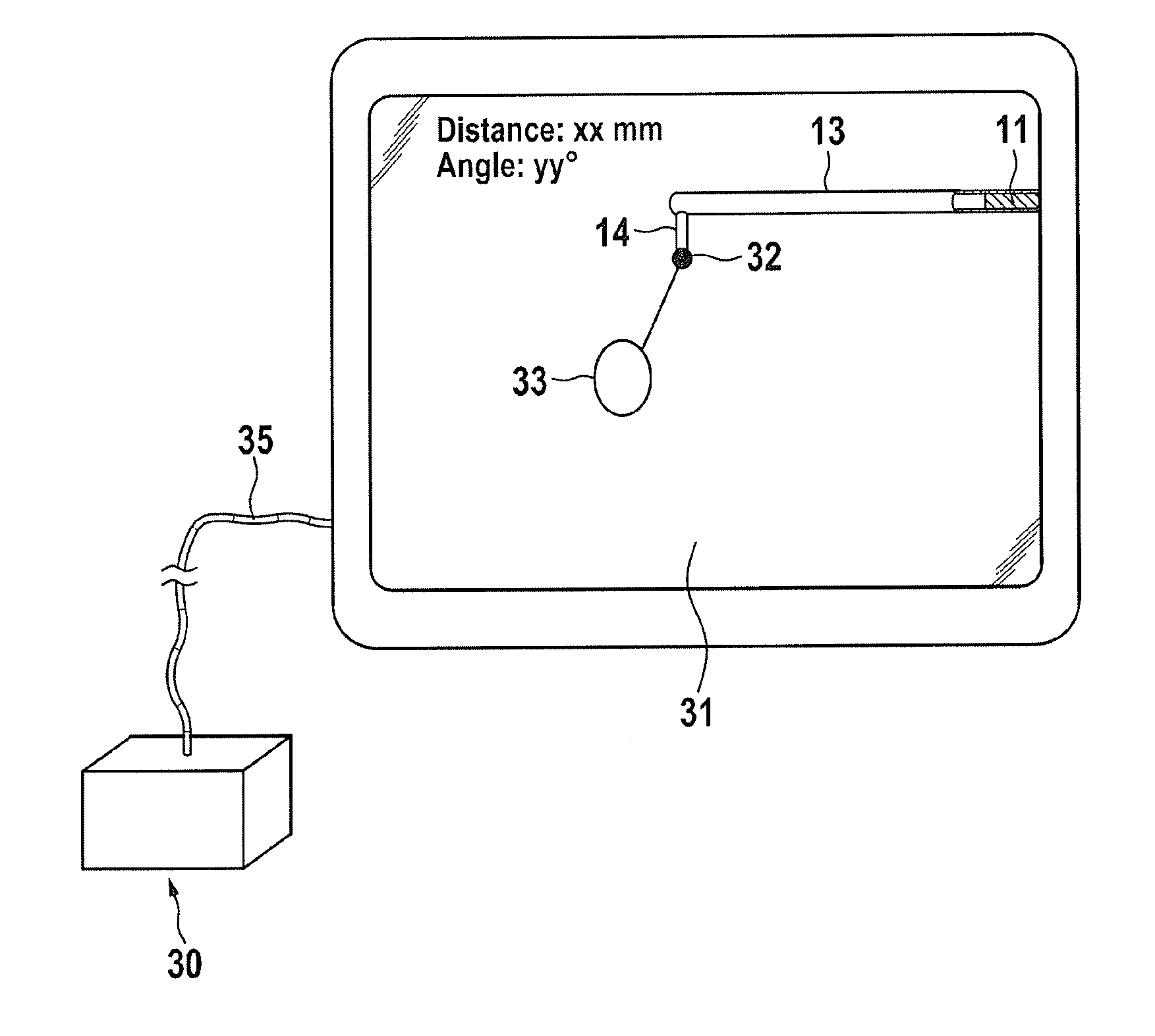
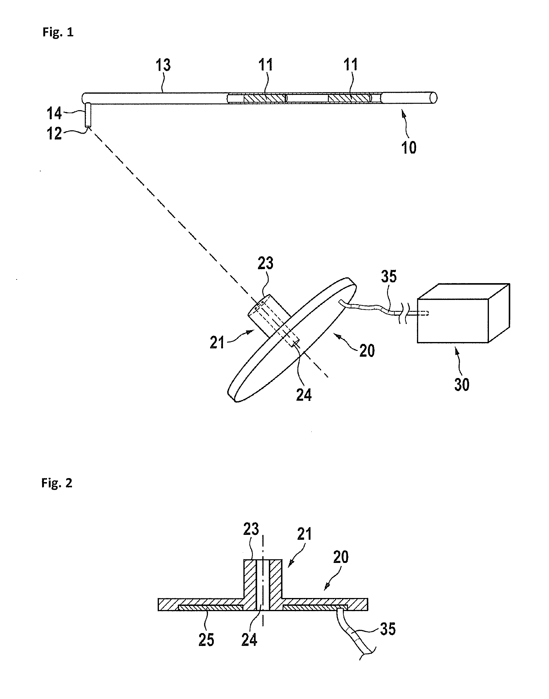
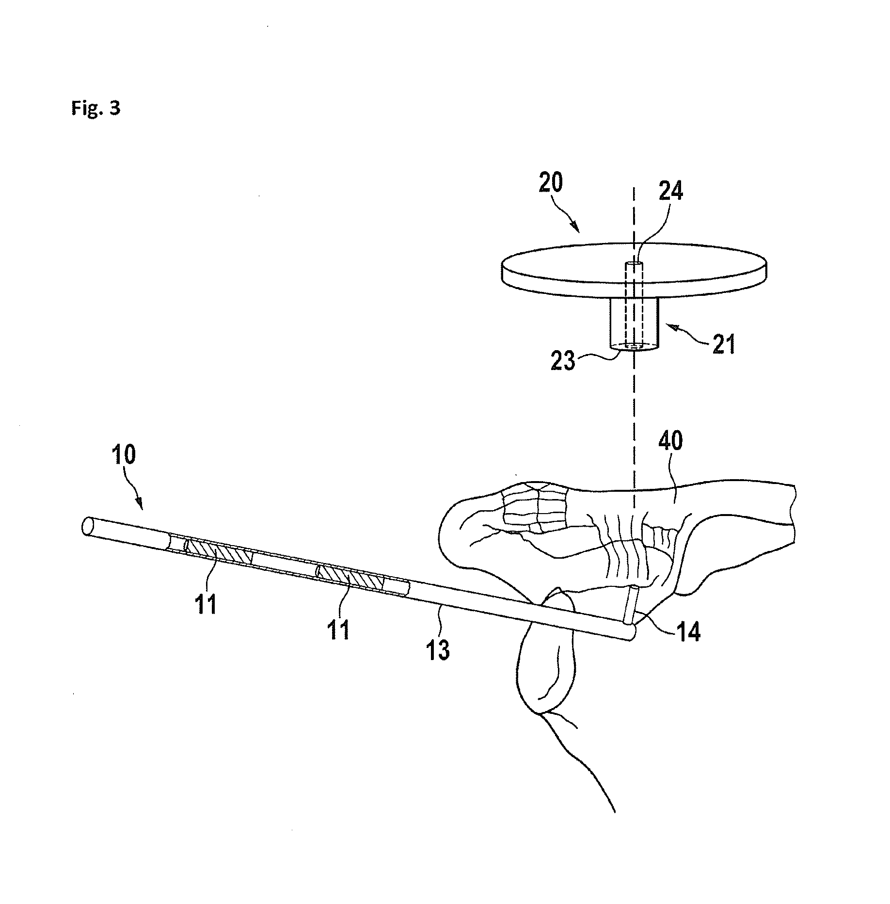
[0032]FIG. 1 shows a first embodiment. A surgical guidance system 1 comprises a probe 10 and targeter 20. FIG. 1 shows a general representation of the probe 10 and targeter 20. As mentioned there are certain surgical techniques and procedures, for example Transcoracoid-Transclavicular Drilling or Retrograde Drilling of Osteochondritis Dissecans Lesions, wherein it is preferable to drill through a portion of body tissue to a desired site within the body of a patient from a side where the desired end of the drill site cannot be seen. In these situations, where a surgeon may desire to drill through a bone of a patient to reach the cartilage in a joint, whilst leaving the cartilage generally undamaged by the drilling process, imaging techniques are required to ensure that the drill has both the correct angle and exit point on the bone. Furthermore, it is important to ensure that the drill does not extend too far past the bone into the tissue which is to be protected, and thus in general...


PUM


Abstract

A surgical guidance system for orthoscopic drilling is disclosed which comprises a probe, the end of which is suitable for locating on the emergence site of a hole to be drilled through body tissue, a targeter comprising one or more sensors for locating the position of the probe, a drill guide, and a control system in communication with the targeter for determining the position of the probe measured by the targeter and providing a real-time visual representation of the relationship between the direction of the drill guide and the tip of the probe to allow the user to align the drill guide to the tip of the probe. The probe comprises an elongate shaft and one or more, preferably two or more markers located at distant positions along the shaft, and wherein further the markers can be detected by the targeter and are each positioned at locations removed from the tip of the probe.

Description

PRIORITY CLAIM[0001]This is a continuation of pending International Application No. PCT / EP2014 / 066946, filed on 6 Aug. 2014, which claims priority from European Application No. 13179418.2, filed on Aug. 6, 2013.BACKGROUND OF THE INVENTION[0002]1. Field of the Invention[0003]The invention relates to a guidance system for precisely locating the direction and the depth of a hole to be drilled into a bone or tissue.[0004]2. Description of Relevant Art[0005]Many surgical techniques, for example those of transcoracoid-transclavicular drilling, preferably require the surgeon to make a bore or drill hole through a portion of the patient's body to a desired site, wherein the end of the bore hole is defined within the patient's body but not visible to the surgeon when drilling. If, for example, a surgeon is required to drill through the bone of the patient into the center of a joint, for example to the underside of the joint cartilage, it is desirable for the drill bore to proceed to the desi...

Claims


Application Information

Patent Timeline
Patent Type & Authority Applications(United States)
IPC IPC(8): A61B34/20A61B17/17
CPCA61B34/20A61B17/1703A61B2090/3983A61B2090/3954A61B2034/2051A61B17/1707A61B2017/00725A61B2017/00738A61B2034/2055A61B2034/2068A61B2034/2072A61B2034/2074A61B2090/363A61B2090/368A61B2090/376A61B2034/107A61B2090/3937A61B2090/3966A61B2034/252A61B17/1778
Inventor MICHEL, GERLINDESTIFTER, JANHOFMANN, MICHAEL
Owner ARTHREX
Why Eureka
Try Eureka