Spectrally-encoded high-extinction polarization microscope and methods of use

a polarization microscope and spectrally encoded technology, applied in the field of polarized light microscopy, can solve the problems of limiting the performance of mpm, degrading the value of recorded data, and speeding up modulation speed

Inactive Publication Date: 2016-06-02
BOARD OF RGT THE UNIV OF TEXAS SYST
View PDF3 Cites 19 Cited by
  • Summary
  • Abstract
  • Description
  • Claims
  • Application Information

AI Technical Summary

Benefits of technology

[0007]Provided herein are systems, methods and apparatuses for a Spectrally-Encoded High-Extinction Polarization Microscope. The polarization microscope generally comprises a variable wavelength light source; a first polarizer optically coupled to the variable wavelength light source, wherein the first polarizer transmits incident light in a pure polarization state; a first retarder module optically coupled to the first polarizer; a specimen stage optically coupled to the first retarder module, wherein the specimen stage holds a specimen in the optical pathway of the light received from the first retarder module; a...

Problems solved by technology

However, lateral movement of cellular objects over the time period of polarization modulation can degrade the value of recorded data.
Therefore, an important factor that limits the performance of MPM is the speed of modulation and the ability of the camera to record high resolution images (both in spatial resolution and bit depth) at rates sufficiently fast to mitigate specimen movement artifacts.
Mechanical rotation of polarizers or 'll-wave plates is limited by the mechanical inertia of the element and is a slow process and frequently introduces mechanical vibration and image blurring.
Furthermore, mechanical rotation of a single element (e.g., a polarizer or 'll-waveplate) may not provide sufficient sampling of the full set of polarization states as visualized on the Poincare sphere and determination of the specimen's components of linear and circular birefringence or other polarimetric signals may not be possible.
Liquid crystal retarders can provide a complete sampling of the Poincare sphere but they are slow and they provi...

Method used


Image

  • Spectrally-encoded high-extinction polarization microscope and methods of use
  • Spectrally-encoded high-extinction polarization microscope and methods of use
  • Spectrally-encoded high-extinction polarization microscope and methods of use

Examples


Embodiment Construction

[0023]The foregoing and other features and advantages of the invention are apparent from the following detailed description of exemplary embodiments, read in conjunction with the accompanying drawings. The detailed description and drawings are merely illustrative of the invention rather than limiting, the scope of the invention being defined by the appended claims and equivalents thereof.

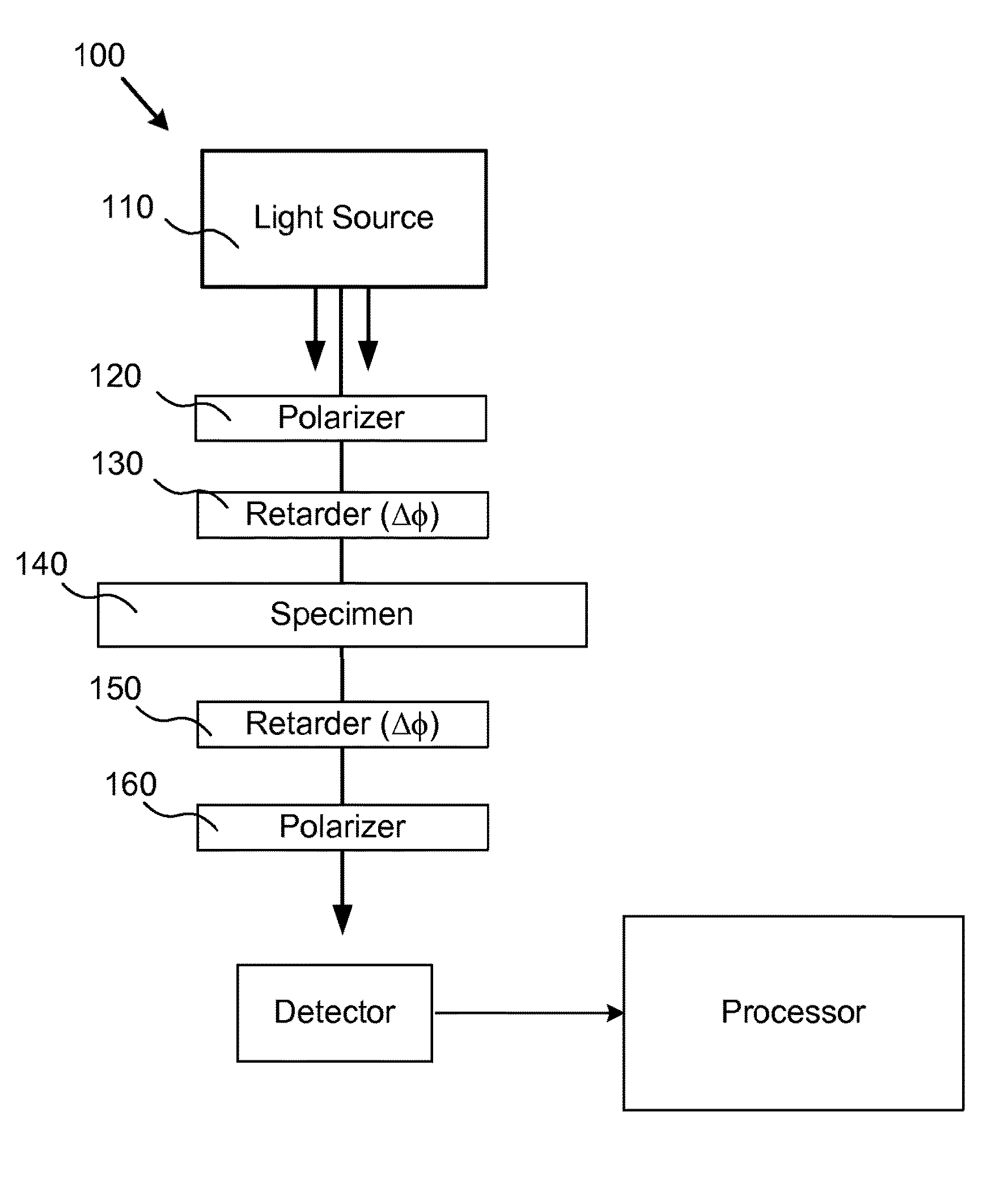
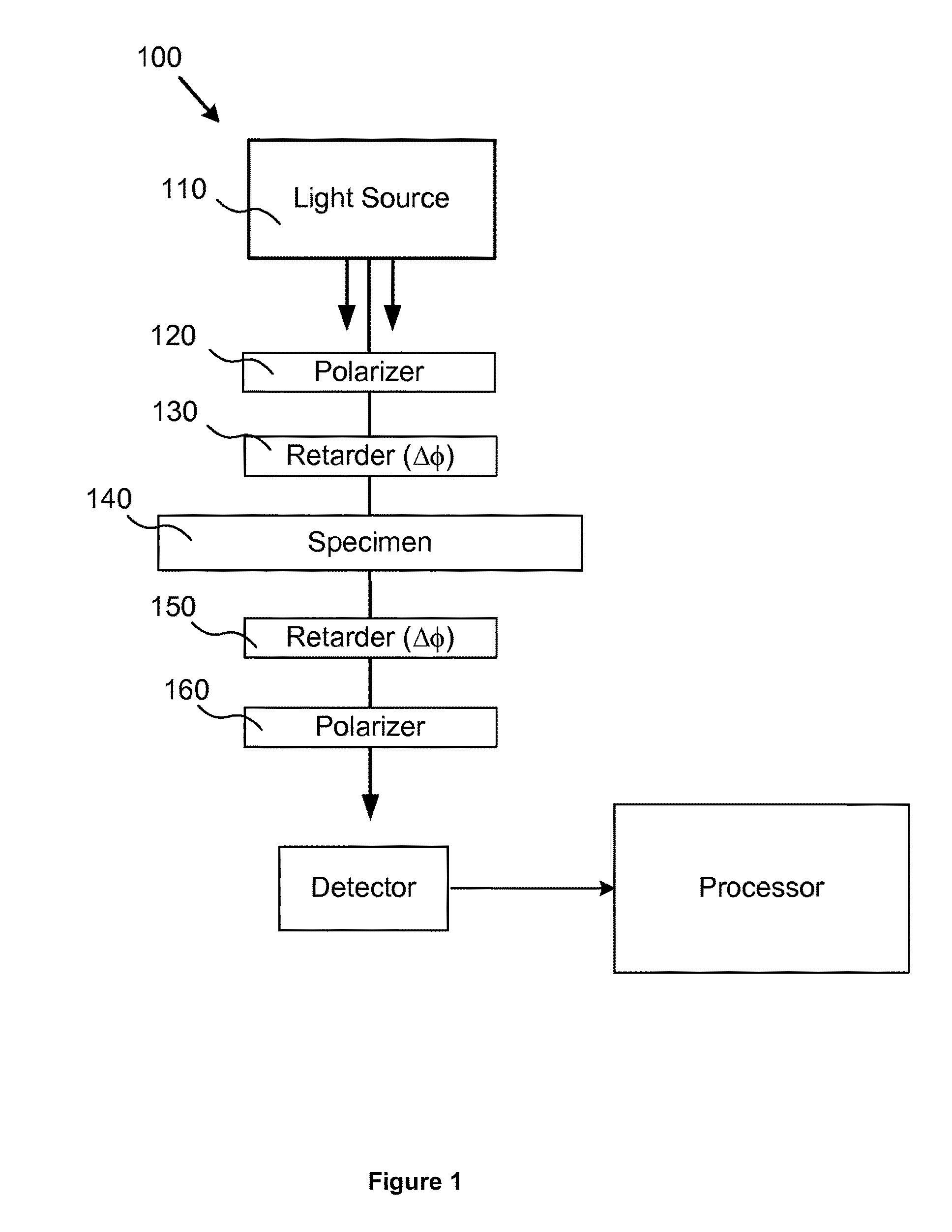
[0024]Embodiments of the invention will now be described with reference to the Figures, wherein like numerals reflect like elements throughout. The terminology used in the description presented herein is not intended to be interpreted in any limited or restrictive way, simply because it is being utilized in conjunction with detailed description of certain specific embodiments of the invention. Furthermore, embodiments of the invention may include several novel features, no single one of which is solely responsible for its desirable attributes or which is essential to practicing the invention describ...


PUM


Abstract

Described herein is a polarization microscope that uses spectral-encoding of the polarization state for cellular imaging. The spectral-encoded polarization microscope is both sufficiently fast for cellular imaging and is compatible with high extinction optics required to image molecular structures and assemblies. The spectral-encoded microscope allows for the polarization state of light presented to the specimen to sample discrete states over the entirety of the Poincaré sphere while simultaneously giving a null measurement of the observed cellular birefringence. Sampling over the entire Poincaré sphere allows the microscope to determine of specimen phase retardation due to both linear and circular birefringence. The spectral-encoded polarization microscope can be operated in a slightly off-null state that will improve signal-to-noise.

Description

CROSS-REFERENCE TO RELATED APPLICATIONS[0001]The present application claims priority from and is a continuation-in-part of PCT Application No. PCT / US2014 / 041570, filed Jun. 9, 2014, which claims priority to U.S. Provisional Application Ser. No. 61 / 832,857, filed Jun. 9, 2013, all of which is incorporated by reference herein in their entireties.BACKGROUND[0002]The invention generally relates to polarized light microscopy.[0003]Cell structures such as polymers, membranes or vesicles are birefringent. Birefringence can be detected and imaged based on how these structures interact with polarized light. However, to fully characterize these interactions, the polarized light must be modulated to allow different polarization states incident on the sample.[0004]Modulated polarization microscopy (MPM) has the demonstrated ability to image cytoskeletal elements and other structures in living cells. Although these structures may be structurally smaller than the resolution of the microscope imag...

Claims


Application Information

Patent Timeline
IPC IPC(8): G02B21/00G02B21/06G06T7/00H04N5/225H04N5/372G02B21/36G02B21/26
CPCG02B21/0092G02B21/36G02B21/06G06T7/0018H04N5/2254H04N5/2256H04N5/372G02B21/26G02B9/04G02B27/28G06T7/80G01N21/23H04N23/56H04N25/71
Inventor MILNER, THOMAS E.YIN, BIWEIKUHN, JEFFREY RUSSEL
Owner BOARD OF RGT THE UNIV OF TEXAS SYST
Why Eureka
Try Eureka