Optical system of a stereo video endoscope with lateral viewing direction and stereo video endoscope with lateral viewing direction

a technology of optical system and endoscope, which is applied in the field of optical system of stereo video endoscope with lateral viewing direction, can solve the problems of insufficient three-dimensional effect, inconvenient endoscopy use, and limited use of stereoscopic optical system in endoscopy, and achieves good and stable imaging, low cost, and large space

Active Publication Date: 2016-06-02
OLYMPUS WINTER & IBE
View PDF29 Cites 9 Cited by
  • Summary
  • Abstract
  • Description
  • Claims
  • Application Information

AI Technical Summary

Benefits of technology

[0018]The distal optical unit thus has at the entry a raised negative meniscus and at the exit a hollow positive meniscus. This combination ensures that 3D distortions are reduced or eliminated. It is thus possible to increase the stereo base in the case of a same-sized or smaller installation size since the stereo image is no longer restricted in its 3D effect by 3D distortions.
[0023]The entrance lens together with the deflection unit can be rotatable with respect to the exit lens, wherein an aperture can be arranged in front of the exit lens. In this case, in which only the entrance lens with the deflection unit is rotatable, improved vignetting is achieved.
[0024]Alternatively, the entrance lens, the deflection unit and the exit lens can be jointly rotatable, wherein an aperture can be arranged after the exit lens. This alternative improves the stability of the focus position when turning the viewing direction.
[0026]In order to achieve good and stable imaging in the lens system channels with simultaneously low costs, each lens system channel of the proximal optical unit can have a plano-convex lens as the first lens and a triplet as the achromatic lens group.
[0027]If the proximal optical unit has one or more optical relay sets, wherein the lens system channels each have one or more optical relay sets or are arranged in front of or behind one or more common optical relay set(s), the separate image information or respectively light bundles of the two lens system channels can be transferred through the endoscope shaft proximally into the handle. Each lens system channel can thereby either have its own relay set or a series of relay sets or a common optical relay set with an overall diameter of the individual lens components of the relay set can be used which is large enough to simultaneously transfer the light beam bundles of both lens system channels. This procedure has the advantage that for example the larger space available in the handle can be used for the use of larger image sensors and / or for further enlargement of the stereo base, i.e. of the distance of the viewing position for the left and right image with respect to each other.

Problems solved by technology

The use of stereoscopic optical systems in endoscopes is currently limited due to the required installation size on straight-ahead looking endoscopes, i.e. on endoscopes with a so-called 0° viewing direction.
This means that it is not suitable for an endoscopic use due to its diameter and the achievable three-dimensional effect is not large enough.
Furthermore, so-called 3D distortions are not corrected sufficiently in the optical system.
As discussed above, this optical system is affected by stronger 3D distortions, which restrict the usable stereo base.

Method used


Image

  • Optical system of a stereo video endoscope with lateral viewing direction and stereo video endoscope with lateral viewing direction
  • Optical system of a stereo video endoscope with lateral viewing direction and stereo video endoscope with lateral viewing direction
  • Optical system of a stereo video endoscope with lateral viewing direction and stereo video endoscope with lateral viewing direction

Examples


Embodiment Construction

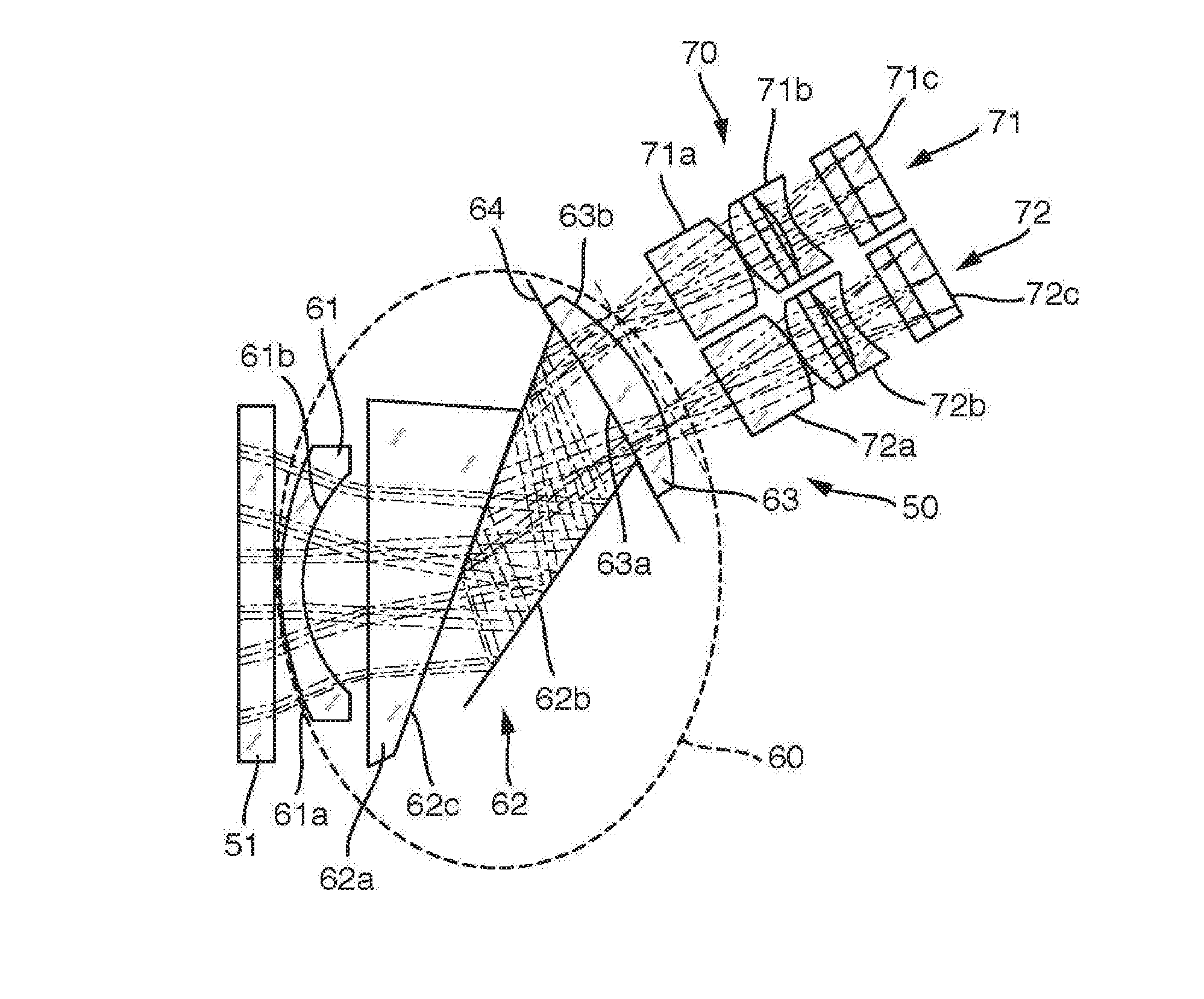
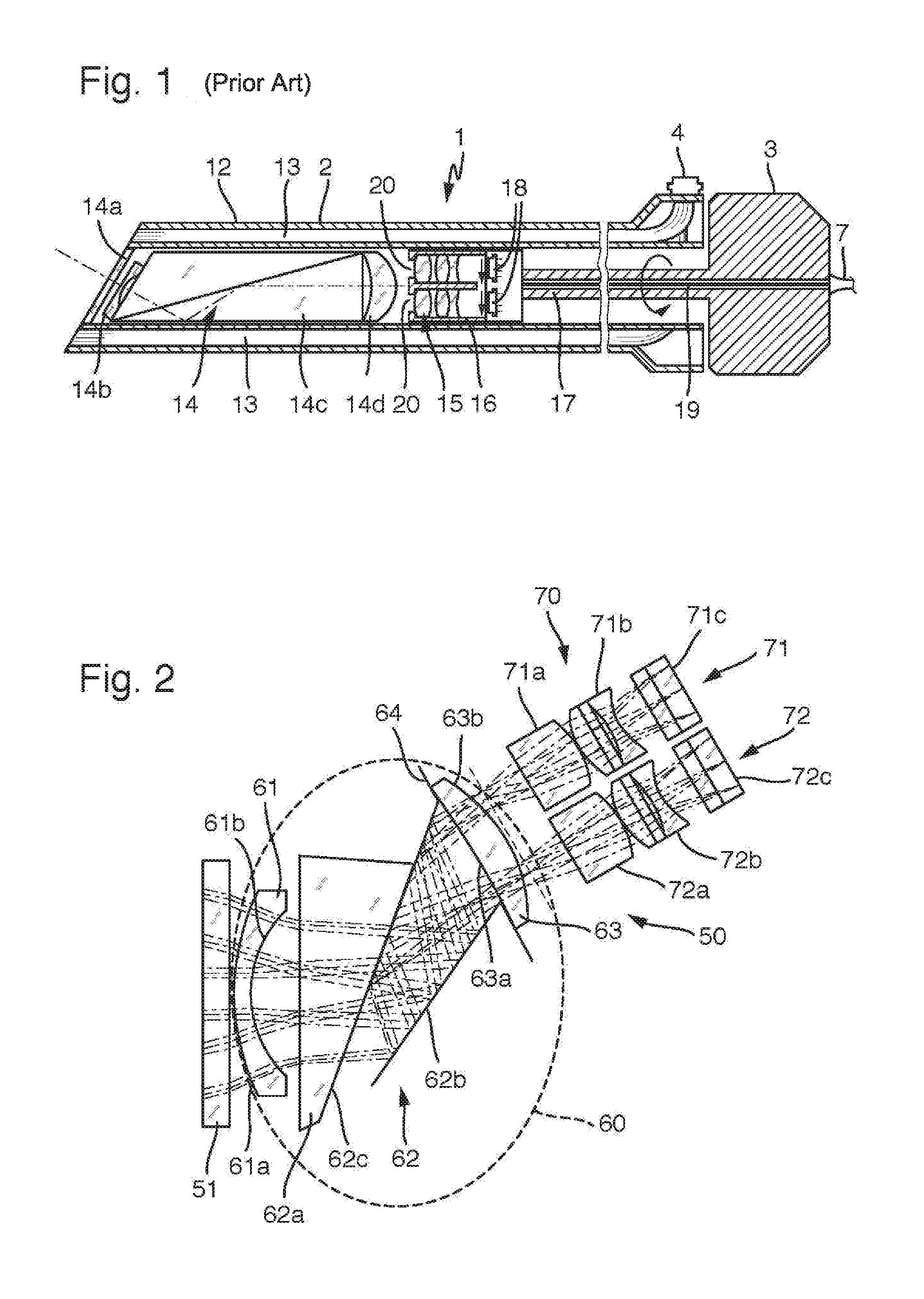
[0041]In contrast to FIG. 1, FIG. 2 shows an optical system 50, which has a distal optical assembly 60 and a proximal optical assembly 70 behind an entrance window 51, which corresponds with the entrance window 14a from FIG. 1. The distal optical assembly 60 comprises an entrance 61, which is embodied as a raised negative meniscus, with a convex left surface 61a and a concave right surface 61b, wherein the descriptions left and right in this context are selected with respect to the conventional theoretical optics definition such that light enters on the left and exits on the right. A deflection unit 62 embodied as a prism unit with two partially mirrored or respectively mirrored boundary surfaces 62b, 62c follows, with which the light entering laterally and diagonally is deflected in the direction of the axis of the endoscope shaft. It is a partially mirrored prism 62a and another prism (not shown in greater detail).

[0042]Behind the deflection unit 62, an exit lens 63 is arranged be...


PUM


Abstract

An optical system of a stereo video endoscope with lateral viewing direction. The optical system including: a sideways looking distal optical assembly; and a proximal optical assembly. Where the distal optical assembly includes, successively in a direction of light incidence on a common optical axis: an entrance lens configured as a raised negative meniscus, an optical deflection unit; and an exit lens configured as a hollow positive meniscus, Where the distal optical assembly has, at least in sections, a right and a left lens system channel of identical type and arranged parallel to one another, each of the right and left lens system channel having: a dedicated optical axis, and at least one first lens and an achromatic lens group in the direction of light incidence.

Description

CROSS-REFERENCE TO RELATED APPLICATION[0001]The present application is a continuation of PCT / EP2014 / 001876 filed on Jul. 8, 2014, which is based upon and claims the benefit to DE 10 2013 215 422.4 filed on Aug. 6, 2013, the entire contents of each of which are incorporated herein by reference.BACKGROUND[0002]1. Field[0003]The present application relates to an optical system of a stereo video endoscope with lateral viewing direction, comprising a sideways looking distal optical assembly and a proximal optical assembly, wherein the distal optical assembly comprises successively in a direction of light incidence an entrance lens, an optical deflection unit and an exit lens, embodied as a hollow positive meniscus, on a common optical axis, wherein the distal optical assembly has at least in sections two right and left lens system channels of identical type and arranged parallel to one another, having in each case a dedicated optical axis, which have in each case in the direction of ligh...

Claims


Application Information

Patent Timeline
Patent Type & Authority Applications(United States)
IPC IPC(8): G02B23/24A61B1/00A61B1/04H04N13/02
CPCG02B23/2415G02B23/243G02B23/2446A61B1/04H04N13/0242A61B1/00193G02B23/2453A61B1/00174A61B1/00096H04N13/243A61B1/044
Inventor ZHAO, JIANXINUZAWA, TSUTOMU
Owner OLYMPUS WINTER & IBE
Why Eureka
Try Eureka