UVC Sterilization Box Electronics Devices

a sterilization box and electronics technology, applied in the direction of measuring devices, electric discharge tubes, instruments, etc., can solve the problems of not always a power source within reach, difficult to handle directly, fragile cold cathode light bulbs, etc., to achieve low wattage cold cathode, easy to clean, and small area available for the bulb

Inactive Publication Date: 2016-06-09
SWEENEY KENNETH GREGORY +1
View PDF5 Cites 14 Cited by
  • Summary
  • Abstract
  • Description
  • Claims
  • Application Information

AI Technical Summary

Benefits of technology

[0011]The present invention includes a new cleaning and sterilization device for remote controls, mobile phones, portable media players, eBook readers and even car keys! This device uses UVC light to kill bacteria and viruses. This device uses low wattage cold cathode UVC bulbs due to the small area available for the bulb. Cold cathode light bulbs are very fragile and are very difficult to handle directly without cracking them or getting hand prints on them. Previous designs of cold cathode based UVC sterilization boxes require the cold cathode bulbs to be handled directly when the bulb is changed out. This is very difficult when the bulbs need to be changed out by people that are not familiar with handling a cold cathode bulb. This new and innovative solution packages the UVC bulbs in a simple, two-part metalized plastic shell which is snapped together and slid into the cleaning box. The entire package slides along the length or height of the UVC cleaning box. There is a simple connector that is attached to the box after it is slid into place and this same connector is disconnected when the bulb assembly is removed. This new UVC bulb cold cathode packaging technique ensures that the cold cathode bulb is never touched directly by human hands when the bulb is being replaced.

Problems solved by technology

Cold cathode light bulbs are very fragile and are very difficult to handle directly without cracking them or getting hand prints on them.
This is very difficult when the bulbs need to be changed out by people that are not familiar with handling a cold cathode bulb.
The problem is that there is not always a power source within reach of the sterilization device.
This is especially true in hospitals where the power plugs are not within reach of a patient in a bed (they are too far down close to the floor).

Method used


Image

  • UVC Sterilization Box Electronics Devices
  • UVC Sterilization Box Electronics Devices
  • UVC Sterilization Box Electronics Devices

Examples


Embodiment Construction

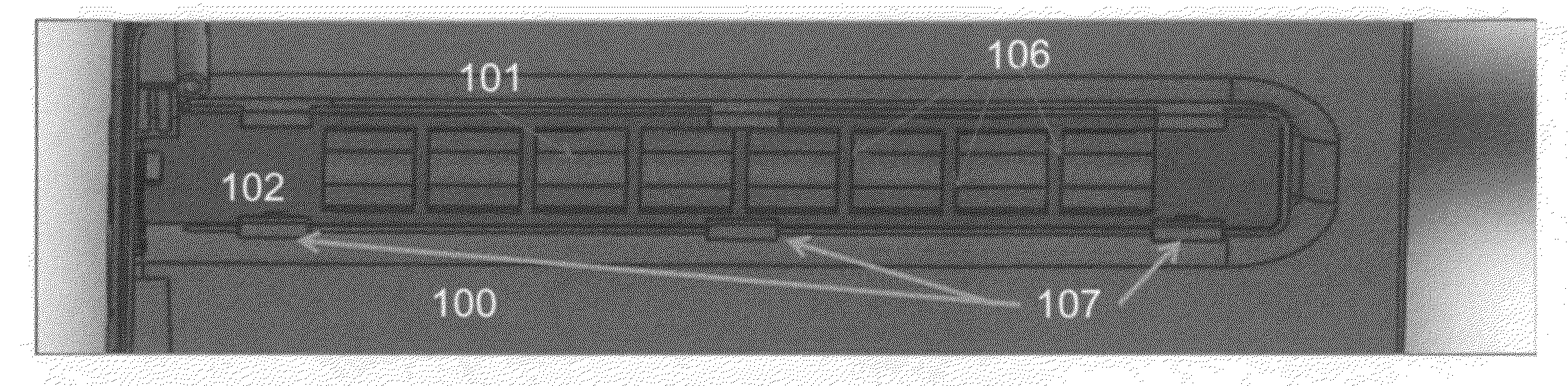
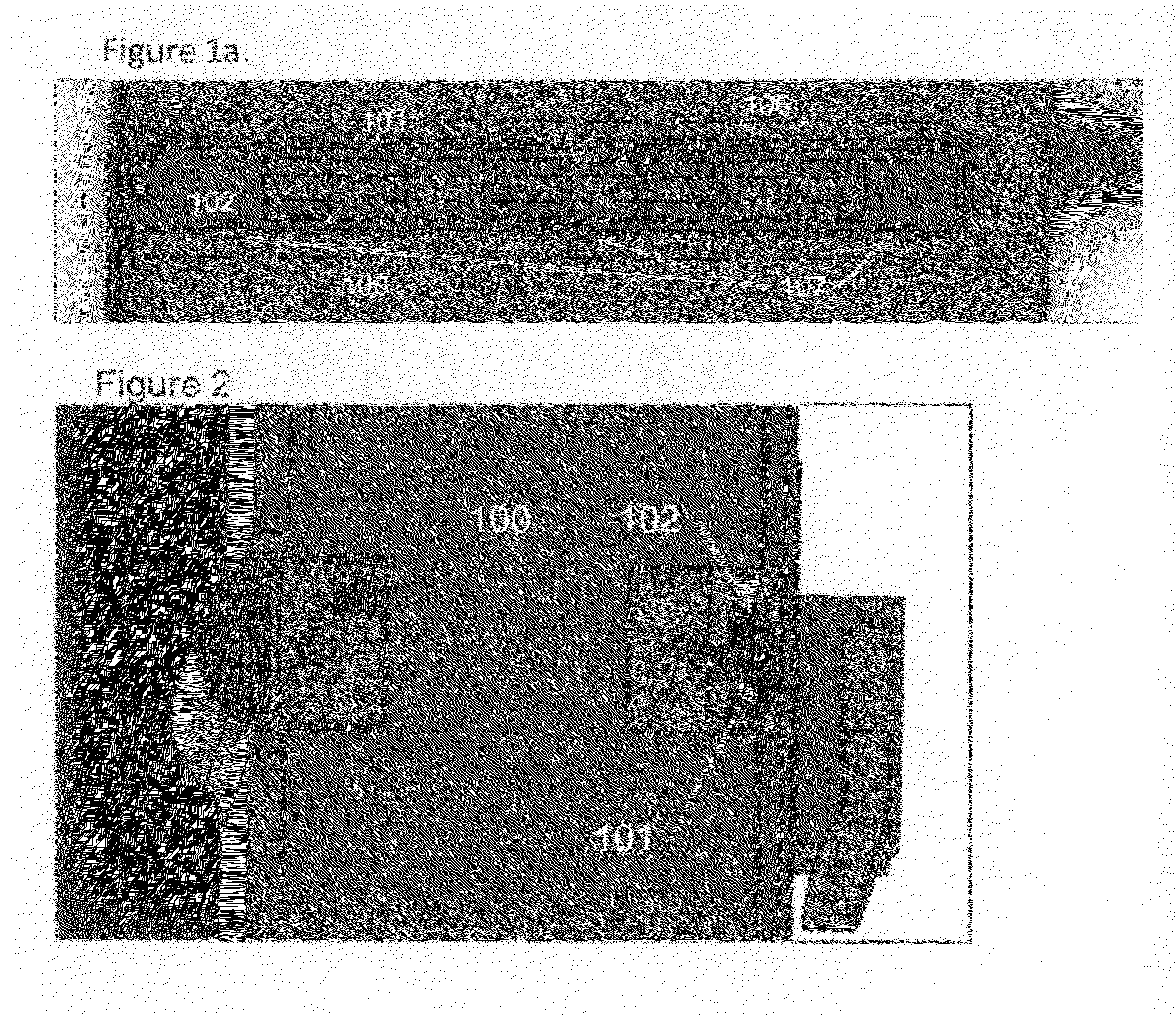
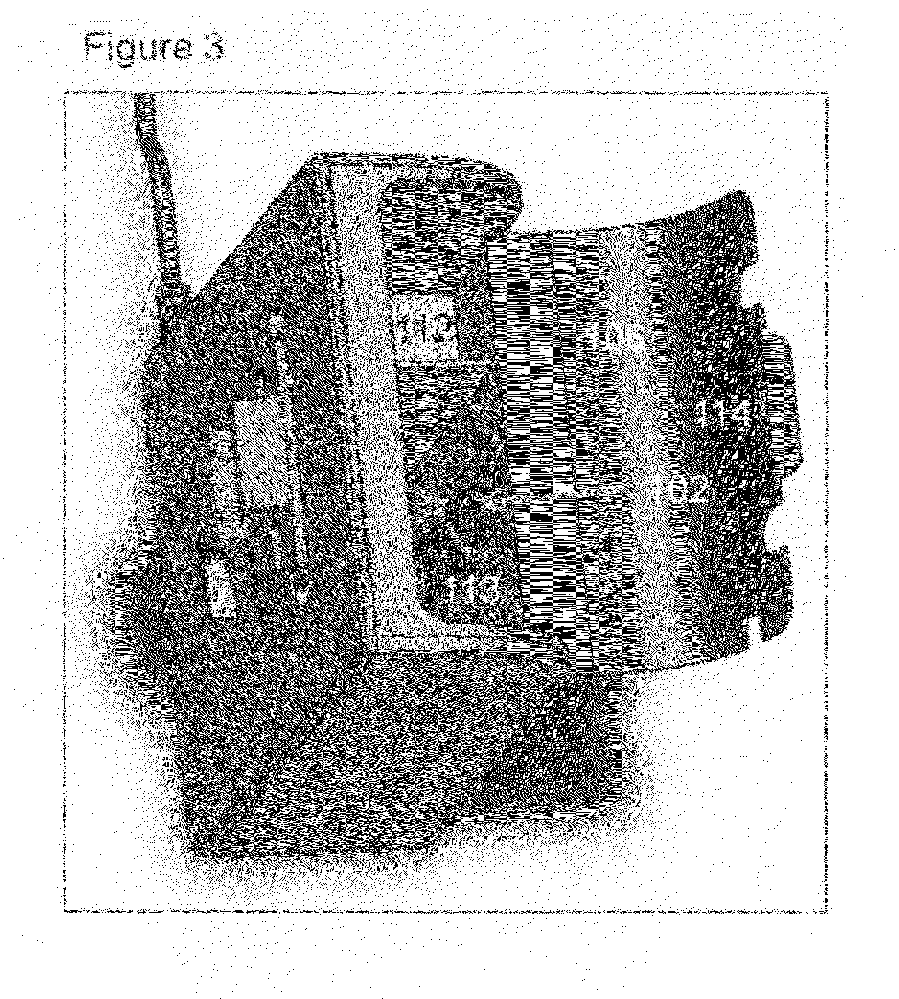
[0024]As mentioned above in this disclosure UVC bulbs that need to fit into smaller boxes for sterilization applications are typically cold cathode UVC bulbs. These bulbs are very small and are very fragile. Their performance is also lessened if hand prints get on the glass part of the bulb, so you do not want human hands with all of the grease and etc. on them to touch the cold cathode UVC bulb during the bulb installation process. We created a separate “package” or enclosure for this UVC bulb 102 which provides the following combined functions for its use inside a UVC sterilization box:[0025]Protects the cold cathode UVC bulb 101 when it is installed.[0026]Ensures no finger prints get on the cold cathode UVC bulb 101 when it is installed.[0027]Provides reflective surface for the UVC bulb 101 when it is in operation inside the sterilization box. The rear side of the plastic package is metalized so that it will reflect all of the light back into the sterilization box[0028]Provides c...


PUM

PropertyMeasurementUnit
254 nanometer wavelengthaaaaaaaaaa
depthaaaaaaaaaa
of timeaaaaaaaaaa

Abstract

A sterilization method and apparatus for cleaning multiple devices of different sizes on all surfaces at one time. This apparatus allows for the cleaning of electronic devices which are corded and cordless/wireless without allowing ozone which is generated from the UV lights to escape from the product or allowing humans eyes to be effected by direct exposure to the UV light generated by the apparatus. This apparatus enables devices to be charged while they are being sterilized. This invention outlines a very simple method for replacement of fragile cold cathode lamps using a wire harness and metalized enclosure

Description

CROSS-REFERENCE TO RELATED APPLICATIONS[0001]Provisional Patent Application No. 61 / 792,673 Dated Mar. 15, 2013 Attached heretoSTATEMENT REGARDING FEDERALLY SPONSORED RESEARCH OR DEVELOPMENT[0002]Not ApplicableREFERENCE TO SEQUENCE LISTING, A TABLE, OR A COMPUTER PROGRAM LISTING COMPACT DISK APPENDIX[0003]Not ApplicableFIELD OF INVENTION[0004]This invention relates to the field of germicidal sterilization or sanitizing of device and / or product surfaces.BACKGROUND OF THE INVENTION[0005]Portable hand held electronics devices like cell phones, cordless phones, remote controls and keyboards are known carriers of bacteria and viruses. They are this way because people touch them often with their hands which they use to touch many other things which carry bacteria. There are specific markets like healthcare where the distribution of multi drug resistant (MDRO) bacteria is a life and death matter.[0006]Today, hospital acquired infections are incurred by one in 20 patients admitted to the hos...

Claims


Application Information

Patent Timeline
Patent Type & Authority Applications(United States)
IPC IPC(8): A61L2/10
CPCA61L2/10H04R1/12
Inventor HUGHES, LOUIS SYLVESTERSWEENEY, KENNETH GREGORY
Owner SWEENEY KENNETH GREGORY
Why Eureka
Try Eureka