Process for isolating microorganisms from samples and system, apparatus and compositions therefor

a microorganism and sample technology, applied in the field of process for isolating microorganisms from samples, can solve the problems of limiting their usefulness, high system cost, and well-adapted, and achieve the effect of lessening or eliminating the effect of magnetic field and magnetic field removal

Inactive Publication Date: 2010-06-10
HER MAJESTY THE QUEEN & RIGHT OF CANADA REPRESENTED BY THE MIN OF HEALTH
View PDF14 Cites 26 Cited by
  • Summary
  • Abstract
  • Description
  • Claims
  • Application Information

AI Technical Summary

Benefits of technology

[0028]To effect movement of the particles into the localized region, the apparatus comprises a magnet that is positioned below the container when the container is in the apparatus. The magnet has a magnetic field localizable at the region on the bottom of the container. The magnet may be a permanent magnet or an electromagnet. The magnet is preferably small having a surface significantly smaller than the bottom of the container, with the size of the magnet determining the size of the localized region. The magnet preferably has a magnetic field large enough to attract particles from the furthest edge of the bottom of the container. The localized region is preferably at the center of the bottom of the container and the magnet is preferably positioned under the center of the bottom of the container.
[0029]The magnetic field generated by the magnet is removable from the region once the magnetic particles have been concentrated there in order to permit retrieval of the magnetic particles without interference from the magnet. The magnet may be physically removed from the region

Problems solved by technology

Such systems are not well adapted for large sample sizes and large volumes of medium, thereby limiting their usefulness in the isolation of some types of microorganisms, e.g. Shigella spp according to Health Canada, Compendium of Analytical Methods for Food and Drug Administration, Bacteriologic Analytical Manual.
Such systems are very expensive, have problems with bead loss on the filters due to

Method used


Image

  • Process for isolating microorganisms from samples and system, apparatus and compositions therefor
  • Process for isolating microorganisms from samples and system, apparatus and compositions therefor
  • Process for isolating microorganisms from samples and system, apparatus and compositions therefor

Examples


second and third embodiments

of Magnetic Particle Collector

[0077]Referring to FIGS. 5A and 5B, second and third embodiments of magnetic particle collectors are now described.

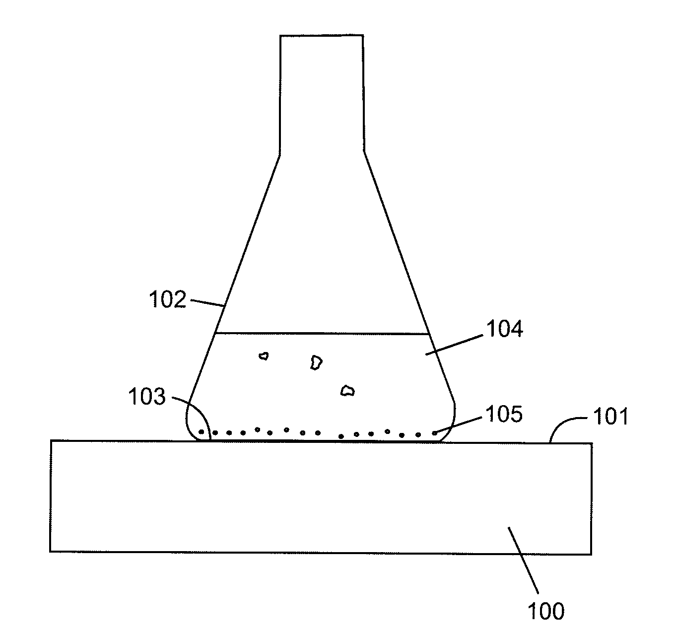
[0078]A second embodiment of a magnetic particle collector as depicted in FIG. 5A comprises a powerful neodymium-iron-boron magnet 405 of a size covering at least half of the surface area of bottom 403 of Erlenmeyer flask 402. The magnet is attached to and sits on the surface of backplate 406.

[0079]A third embodiment of a magnetic particle collector as depicted in FIG. 5B comprises a powerful samarium-cobalt magnet 415 of a size covering at least half of the surface area of bottom 413 of Erlenmeyer flask 412. The magnet is recessed in the surface of backplate 416.

[0080]In both the second and third embodiments of the magnetic particle collector, the backplate has the following features. It comprises a material of high magnetic permeability and susceptibility, for example mild steel or transformer iron. It is larger than the magnet and is app...

third embodiment

of Magnetic Particle Concentrator

[0082]Referring to FIGS. 6A-6F, a third embodiment of the magnetic particle concentrator is now described.

[0083]Referring specifically to FIGS. 6A and 6B, a tilting frame 814, illustrated in plan in FIG. 6A and in section in FIG. 6B along line A-A in FIG. 6A, carries magnet assembly generally denoted at 802. Tilting frame pivots on pivot 815 allowing magnet assembly 802 to be raised to a raised position (solid lines in FIG. 6B) and lowered to a lowered position (dotted lines in FIG. 6B) as required so that it is either in contact with the centre of the bottom of flask 801 or far enough away that the magnetic field has a negligible effect on magnetic particles in the flask. Actuation of handle 817 raises and lowers tilting frame 814. A suitable detent means is be used to keep the tilting frame and therefore the magnet assembly in either the raised or lowered positions.

[0084]Magnet assembly 802 produces a strong magnetic field in a direction more or le...

second embodiment

of Magnetic Particle Pipette

[0089]FIGS. 7A-7C illustrate a second embodiment of a magnetic particle pipette in which FIG. 7A depicts various components of the pipette disassembled into three parts for clarity, FIG. 7B depicts an assembled pipette in a rubber tip-attaching configuration and FIG. 7C depicts the assembled pipette in a rubber-tip detaching configuration.

[0090]Tubular pipette body 921, conveniently of circular cross-section and of any suitable material (e.g. metal or rigid plastic), has slot 922 in a higher region of the tubular pipette body such that first knob 926 attached to slider 925 can move freely up and down. A smaller diameter section 935 in a lower region of the tubular pipette body has a diameter such that it can removably grip rubber tip 923. Rubber tip 923, fabricated of inert elastic material, is tapered and is closed at its narrow end. The rubber tip is conveniently a commercially available product sold under the trade name PickPen™ Tip by BIOCONTROL Syste...


PUM


Abstract

A process for isolating microorganisms from samples, particularly Shigella spp. from food samples, and a system, apparatus and composition therefor are provided. Magnetic particles are used to capture microorganisms and a system having separate magnetically-based apparatuses for collecting, concentrating and retrieving is used to isolate the magnetic particles having bound microorganisms. The apparatus for concentrating magnetic particles utilizes a small magnet assisted by vibration to concentrate collected particles at a localized region on the bottom of a container. The process, system and apparatus of the present invention are simple and inexpensive providing improved magnetic particle recovery adaptable to large scales.

Description

CROSS-REFERENCE TO RELATED APPLICATIONS[0001]This application claims the benefit of U.S. provisional patent application U.S. Ser. No. 60 / 924,001 filed Apr. 26, 2007, the entire contents of which is herein incorporated by reference.FIELD OF THE INVENTION[0002]The present invention relates to a process for isolating microorganisms from samples, particularly food samples, and a system, apparatus and composition therefor.BACKGROUND OF THE INVENTION[0003]The use of magnetic particle technology, particularly antibody-coated magnetic beads (immunomagnetic beads), for the selective isolation of microorganisms in microbiology in general and in food and environmental microbiology in particular is becoming more widely used. Different systems and individual pieces of equipment have been developed to assist in the use of magnetic particles.[0004]Many systems have been developed for collecting magnetic beads from small scale volume samples. Such systems typically handle samples of volumes from 1 ...

Claims


Application Information

Patent Timeline
IPC IPC(8): C12N13/00C12M1/42
CPCB03C1/288C12N1/02C12Q1/24C12M33/08G01N33/54326G01N33/569G01N33/56916G01N33/02B03C2201/26
Inventor BIN KINGOMBE, CESAR G. I.SHARPE, ANTHONY N.
Owner HER MAJESTY THE QUEEN & RIGHT OF CANADA REPRESENTED BY THE MIN OF HEALTH
Why Eureka
Try Eureka