Rotary airlock valve

a technology of airlock valve and sealing surface, which is applied in the direction of measuring device, loading/unloading, instruments, etc., can solve the problems of gas leakage outside the housing, wear and tear of the sealing surface of the rotary airlock valve, etc., to reduce the wear effect of the housing wall and associated seal, the effect of reducing the quantity of captured steam

Active Publication Date: 2005-11-22
ASJ HLDG
View PDF8 Cites 26 Cited by
  • Summary
  • Abstract
  • Description
  • Claims
  • Application Information

AI Technical Summary

Benefits of technology

[0008]It is an object of the present invention to provide a rotary airlock valve with reduced wear characteristics.
[0009]It is a further object of the present invention to provide a rotary airlock valve that can readily handle steam expansion effects without increased wear.
[0014]By outwardly narrowing the forward edge, and then expanding to a wider trailing edge, any expansion of gas or particle acceleration is directed by the narrow forward edge away from the side edges of the housing, to reduce the wear effects on the housing walls and associated seals. Once the pressure is depleted, the wider trailing edge assures that all the material in the pocket is discharged.
[0015]In another embodiment, the pockets have side walls converging from an inner end to an outer end thereof, to add tapering to the entire pocket. In yet another embodiment, the leading edges of each pocket are displaced slightly relative to each other, for example starting close to a first side of the housing and moving in staggered increments across the width of the cylinder to distribute the wear effects across the entire width of the cylinder, while still obtaining the benefit of the narrowed forward edge design. In this way, the life of the rotary airlock valve can be extended even further.
[0016]Preferably, multiple small chambers are defined by the vanes as opposed to a few large chambers, as this further reduces the quantity of captured steam within any one pocket. Preferably, more than 6 pockets are provided, most preferably about 7 to 12 pockets are used. The forward edge preferably has a width that is about 50 to 80% of the width of the cylinder, the trailing edge having a width of from 75 to 100% of the width of the cylinder. Also, The taper angle of the side walls of the pocket can vary and is preferably an angle greater than 2 degrees of the circle of the revolution.

Problems solved by technology

However, there are problems with rotary airlock valves in such an application, particularly due to wear.
Whenever solids transfer occurs, there is a potential for the sealing surfaces to wear, resulting in gas by-pass around the rotary air valve.
This is a particularly serious problem when handling pulp, as this may contain sand, which is quite abrasive.
Also, the rotary airlock valve typically includes a seal or gasket between the rotating vanes and the static housing portions, and any solids incursion can lead to rapid wear, that can result in gas leaks outside of the housing.
When such leakage occurs, the system must be shut down, resulting in costly processing delays.
Typically, such rotary airlock valves have a very limited life in the harsh pulp service described above, of about two months.
This problem is particularly acute when the rotary airlock valve transfers a dried solid material from a pressure of about 2.5 bar, to atmospheric pressure, with superheated steam being the pressurizing gas.
As the shaft rotates to the discharge opening, the initial breach to the low pressure side causes a strong outflow of steam, causing the dried material be accelerated as it is driven out of the pocket, at velocities of up to 300 meters per second, increasing the abrasive effect and wear on the adjacent parts, particularly the edge of the opening.
In addition, the flashing of the steam from the pocket can cause condensation and wetting of the powder material or adjacent surfaces, that may lead to product accumulation.
With each successive turn of the room, the expansion effect increases due to a wearing of the sealing surfaces, eventually resulting in a gas by-pass around the valve.

Method used


Image

  • Rotary airlock valve
  • Rotary airlock valve
  • Rotary airlock valve

Examples


Embodiment Construction

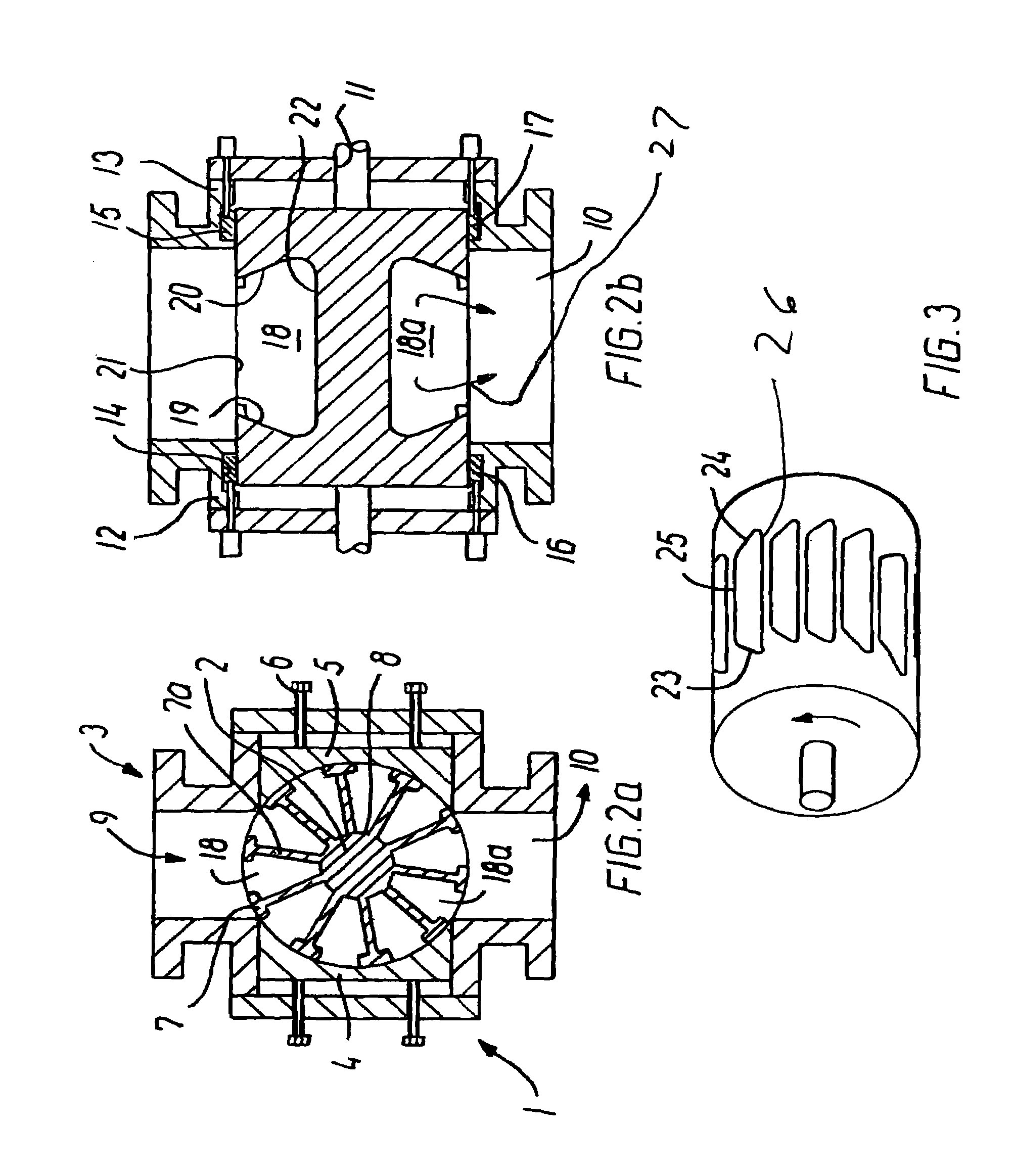
[0021]Referring to FIG. 2a, a rotary airlock valve 1 has a rotor 2 disposed in a housing 3 having a pair of movable cylindrical sealing walls 4 and 5. These are adjusted by screws 6 to assure a positive seal with vanes 7 that extend from a hub 8 of the rotor. The housing has an inlet opening 9 and an outlet opening 10. Referring to FIG. 2b, the rotor is mounted to a shaft 11, driven for rotation by a motor (not shown). The housing has a side sections 12 and 13, each having a circumference groove 14 and 15 that receive a sealing material or gasket 16 and 17 therein. The sealing material may be a gasket, a compressible packing, or any other conventional seal commonly used to seal such rotating parts.

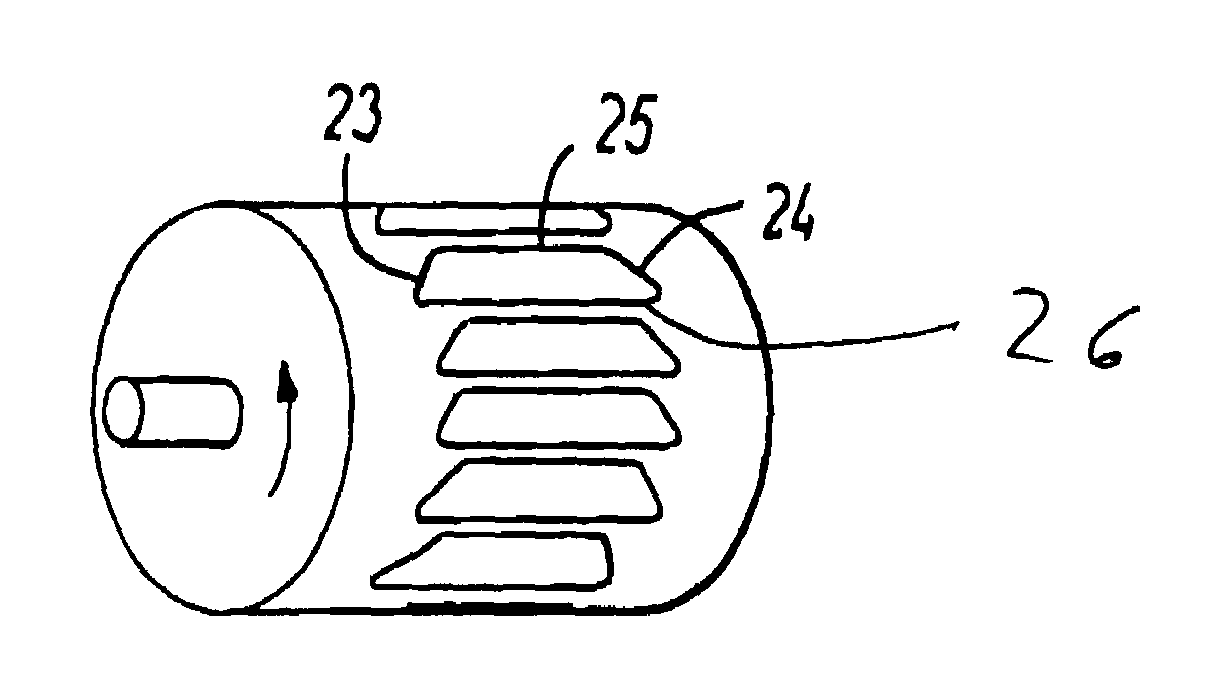
[0022]In FIG. 2b, a material receiving pocket 18 is shown adjacent the inlet opening for receiving a solid material therein. The pocket shape is defined by the adjacent vanes, 7 and 7a, and has converging side walls 19 and 20 such that the pocket opening 21 is of smaller cross-section than...


PUM


Abstract

A rotary airlock valve has a plurality of material receiving pockets having leading edges that are narrower than the trailing edges thereof, preferably having walls tapering inwardly so as to define a narrowed pocket opening for directing any material expansion due to pressurization to a center of a discharge outlet, to reduce wear and increase seal life.

Description

TECHNICAL FIELD[0001]This invention relates to a rotary airlock valve and more particularly to a rotary airlock valve for transferring a solid material from a high gas pressure entrance thereof to a low gas pressure discharge.BACKGROUND[0002]Rotary airlock valves are well known for use in the solids handling industry. Often, a solid material is transported to or received in a vessel using a pressurized gas such as air. The solid material accumulates in the vessel which remains under pressure. The typical way to remove the solid material is for it to collect in a discharge area or hopper which leads to an entrance of the rotary airlock valve.[0003]A rotary airlock valve typically comprises a housing containing a cylindrical chamber within which is mounted an axially extending shaft. The shaft has a plurality of radially extending vanes or blade portions, with material receiving pockets defined between the vanes. As the shaft rotates, the outer edges of the vanes sealingly engage the ...

Claims


Application Information

Patent Timeline
Patent Type & Authority Patents(United States)
IPC IPC(8): G01F11/10B65G53/46B65G65/48G01F11/24
CPCB65G53/4633B65G65/4881G01F11/24
Inventor JENSEN, ARNE SLOTH
Owner ASJ HLDG
Why Eureka
Try Eureka