External-perfusion hollow-fiber membrade module and inkjet printer having said module

a technology of hollow fiber membrane and inkjet printer, which is applied in the direction of membranes, liquid degasification, separation processes, etc., can solve the problems of quality defects or reduced discharge accuracy of printed matter, and achieve the effects of preventing flaws, stable performance, and suppressing production costs

Active Publication Date: 2016-06-09
MITSUBISHI CHEM CORP
View PDF4 Cites 11 Cited by
  • Summary
  • Abstract
  • Description
  • Claims
  • Application Information

AI Technical Summary

Benefits of technology

[0030]According to the invention, since a hollow-fiber membrane bundle is fixed to the inside of a casing at one end thereof and the other end thereof is a free end, a liquid easily enters between the hollow-fiber membranes, and degassing or gas-liquid mixing can be effectively performed. In addition, since one potting portion exists in the casing, it is possible to suppress production costs and achieve miniaturization.
[0031]In the case of the configuration (2) described above, from the configuration where the homogeneous layer with the gas permeability is protected by the porous support layer, it is possible to prevent flaws in a working process and provide stable performance.
[0032]In the case of the configuration (3) described above, when the liquid flows to the outside of the hollow-fiber membrane, it is possible to further effectively form a flow channel in an insertion state of the hollow-fiber membrane.
[0033]In the case of the configuration (4) described above, the strength necessary for a process of aligning the length of the hollow-fiber membrane bundle is obtained, and thus it is possible to prevent damage in a production process and perform an effective and inexpensive membrane bundle forming process.
[0034]In the case of the configuration (5) described above, it is possible to provide appropriate voids between the hollow-fiber membranes, the void being required to effectively flow the liquid to the outside of the hollow-fiber membrane.
[0035]In the case of the configuration (6) described above, the flow channel of liquid is formed over one end from the other end of the hollow-fiber membrane bundle, and thus it is possible to perform the degassing or the gas-liquid mixing using effectively the hollow-fiber membrane bundle over the wide range and to improve the efficiency of the degassing or the gas-liquid mixing.

Problems solved by technology

At this time, when the chemical liquid contains air bubbles, there is a case where discharge accuracy is reduced or quality defects occur in a printed matter.

Method used


Image

  • External-perfusion hollow-fiber membrade module and inkjet printer having said module
  • External-perfusion hollow-fiber membrade module and inkjet printer having said module
  • External-perfusion hollow-fiber membrade module and inkjet printer having said module

Examples


first embodiment

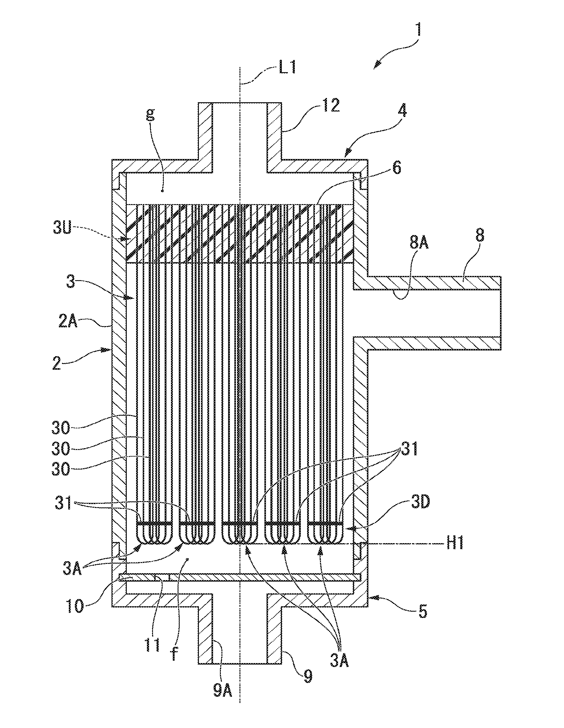
[0069]FIG. 1 illustrates a degassing module 1 of an external perfusion type according to a first embodiment of the invention. The degassing module 1 includes a casing 2 and a hollow-fiber membrane bundle 3 housed in the casing 2. The casing 2 includes a cylindrical casing body 2A, a first cover member 4 for covering one end opening of the casing body 2A, and a second cover member 5 for covering the other end opening of the casing body 2A.

[0070]The casing 2 is formed to have substantially a columnar appearance by coupling of the casing body 2A, the first cover member 4, and the second cover member 5. The degassing module 1 is intended to be used in an inkjet discharge apparatus such as an inkjet printer or a color filter manufacturing apparatus, but there is no specific limitation on its use.

[0071]In the drawing, reference numeral L1 indicates a central axis of the casing 2 (hereinafter, simply also referred to as a center) extending in an axial direction of the casing 2 through a cr...

second embodiment

[0156]FIG. 6 illustrates a degassing module 1′ according to a second embodiment of the invention. In the second embodiment, the same components as in the first embodiment denote the same numeral references, and the description thereof will not be presented.

[0157]In the degassing module 1′ according to the second embodiment, a casing 2 does not include a dispersion plate 10. In addition, a first cover member 4 is disposed at a lower side to be formed with a vacuum port 12, and a second cover member is disposed at an upper side to be formed with a second port 9 functioning as an inflow port through which liquid flows in. Then, the degassing module 1′ is configured to flow the liquid downward from the second port 9 toward the first port 8. Reference numeral L1′ represents a central axis passing through a cross-sectional center of the casing 2 (casing body 2A). The casing 2 may be a circular cylindrical body in cross section and may be, for example, a rectangular hollow body in cross se...

third embodiment

[0161]FIG. 7 illustrates an external-perfusion degassing module 1a according to a third embodiment of the invention. In the third embodiment, the same components as in the first embodiment denote the same numeral references, and the description thereof will not be presented.

[0162]In the degassing module 1a according to the third embodiment, a casing 2 does not include a dispersion plate 10. A first port 8 is located above a potting portion 6 to function as an outflow port through which liquid flows out, and protrudes radially outward from an outer peripheral surface of a casing body 2A. In addition, a second port 9 is located above the potting portion 6 to function as an inflow port through which liquid flows in, and protrudes radially outward from the outer peripheral surface of the casing body 2A. The first port 8 and the second port 9 are located at a distance from each other in a horizontal direction. In this embodiment, the first port 8 and the second port 9 are disposed such t...


PUM

PropertyMeasurementUnit
outer diameteraaaaaaaaaa
fracture elongationaaaaaaaaaa
outer diameteraaaaaaaaaa

Abstract

The present invention relates to a external-perfusion hollow-fiber membrane module containing a hollow-fiber membrane bundle including a plurality of hollow-fiber membranes; and a casing that houses the hollow-fiber membrane bundle, wherein the hollow-fiber membrane bundle has one end that is fixed to an inside of the casing by a potting portion in an open state, and the external-perfusion hollow-fiber membrane module is configured to perform degassing on a gas contained in a liquid inside the casing, the gas being introduced into an inside from an outer surface of the hollow-fiber membrane.

Description

TECHNICAL FIELD[0001]The present invention relates to an external-perfusion hollow-fiber membrane module and an inkjet printer having the module.[0002]This application is based upon and claims the benefit of priority of the prior Japanese Patent application No. 2013-153865 which has been filed in Japan on Jul. 24, 2013, and the prior Japanese Patent application No. 2013-153866 which has been filed in Japan on Jul. 24, 2013, the entire contents of which are incorporated herein by reference.BACKGROUND ART[0003]A module using a hollow-fiber membrane (hereinafter, referred to as a hollow-fiber membrane module) has been known from the past. Examples of the hollow-fiber membrane modules include an internal-perfusion type in which a liquid passes through the inside of a hollow-fiber membrane and an external-perfusion type in which a liquid passes through a periphery (outside) of a hollow-fiber membrane depending on the difference in passage paths of liquid. Patent Documents 1 and 2 disclos...

Claims


Application Information

Patent Timeline
Patent Type & Authority Applications(United States)
IPC IPC(8): B01D19/00B01D63/04B41J2/175B01D63/02
CPCB01D19/0031B01D63/024B01D2313/08B41J2/17563B01D63/04B01D63/02B01D2313/00B01D2313/10B41J2/19
Inventor TANIZAKI, YOSHIEOKAZAKI, HIROYUKI
Owner MITSUBISHI CHEM CORP
Why Eureka
Try Eureka