Low drag skin heat exchanger

Active Publication Date: 2016-06-09
PARKER HANNIFIN CORP
View PDF6 Cites 18 Cited by
  • Summary
  • Abstract
  • Description
  • Claims
  • Application Information

AI Technical Summary

Benefits of technology

[0004]The present invention provides a heat exchanger including a heat exchange panel having an exterior surface that forms an exterior surface of the vehicle (e.g. an aircraft), the heat exchange panel having at least a portion made of a thermally conductive material, and one or more vortex g

Problems solved by technology

These heat exchangers tend to be heavy, which red

Method used


Image

  • Low drag skin heat exchanger
  • Low drag skin heat exchanger
  • Low drag skin heat exchanger

Examples


Embodiment Construction

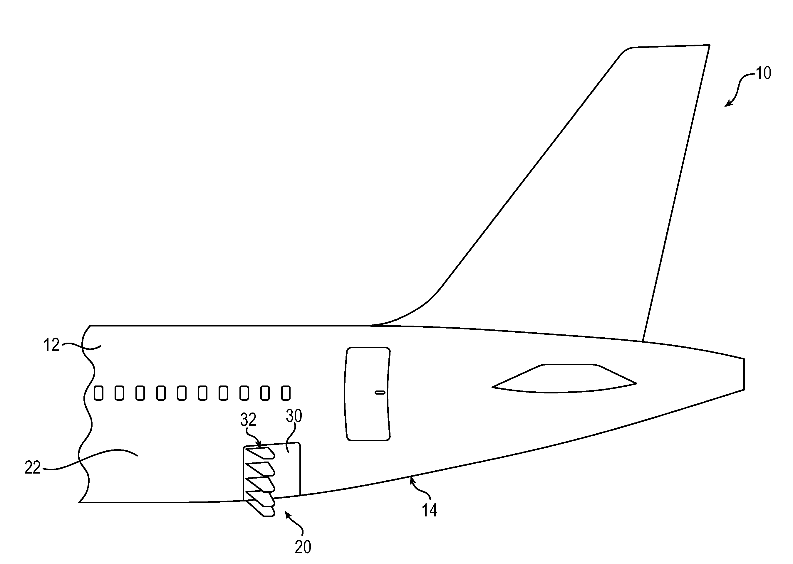
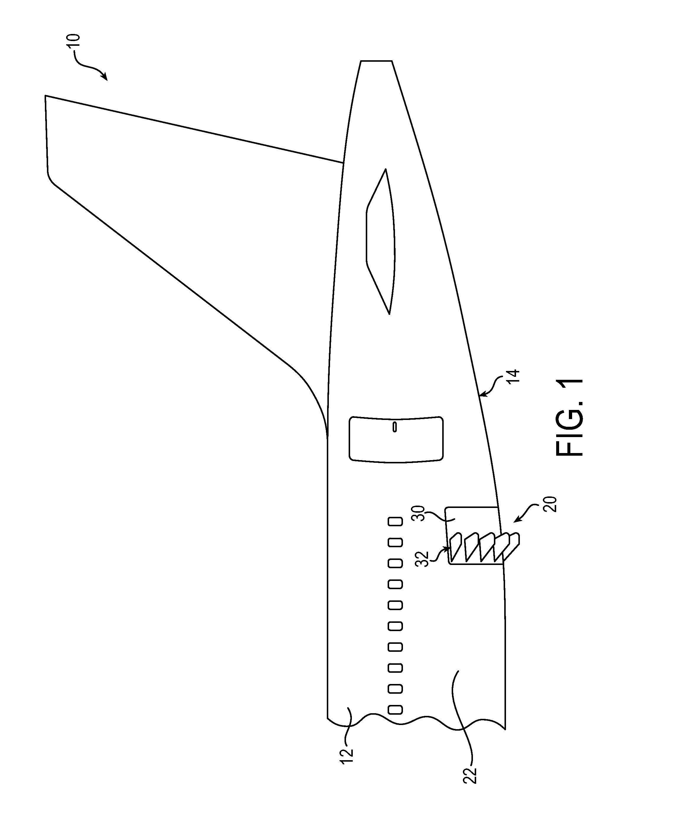
[0072]The principles of this present application have particular application to heat exchangers for vehicles, such as an aircraft, and thus will be described below chiefly in this context. It will of course be appreciated, and also understood, that principles of this invention may be applied in other applications where both heat transfer and reduced drag are desired.

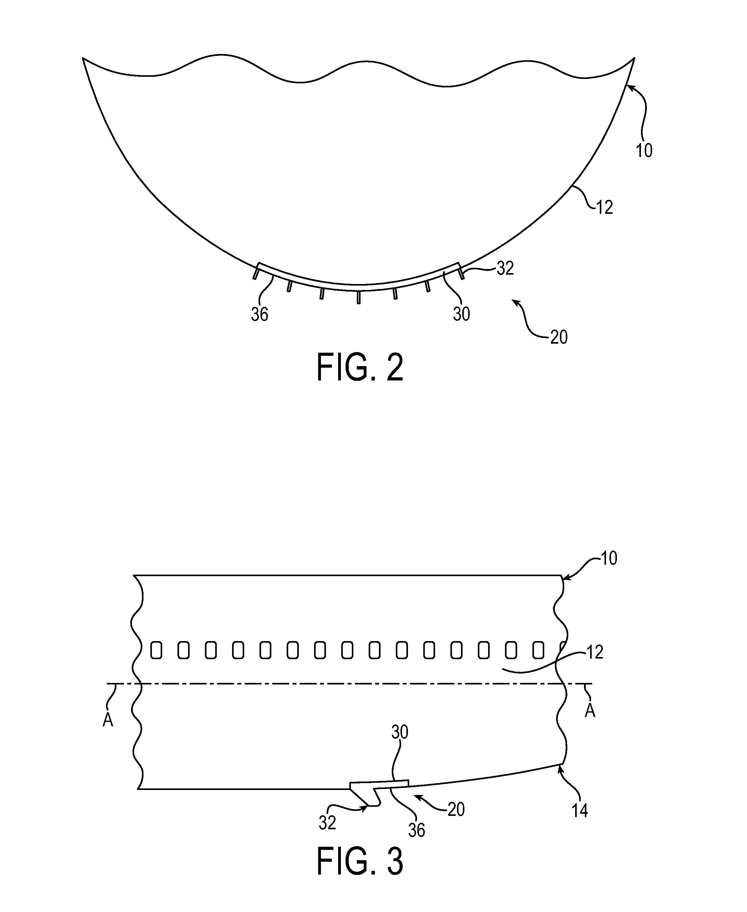
[0073]Referring now in detail to the drawings, and initially to FIG. 1, an aircraft 10 is illustrated. The aircraft 10 may be of any type, such as a commercial airliner. The aircraft 10 may include an outer skin 12 forming an outer surface of the aircraft 10, an empennage upsweep 14, and a heat exchanger 20. The heat exchanger 20 may be disposed on or flush with the outer skin 12. The heat exchanger 20 includes a heat exchange panel 30 and a plurality of vortex generators 32. The vortex generators 32 may be positioned for optimal heat transfer. For example, the vortex generators 32 may be disposed at an end of the heat e...


PUM


Abstract

The present invention provides a heat exchanger including a heat exchange panel configured to form an exterior surface of the vehicle (e.g. an aircraft), the heat exchange panel having at least a portion made of a thermally conductive material, and one or more vortex generators protruding from the exterior surface and configured to direct airflow to particular areas on the aircraft, which may then prevent large scale airflow separation. The vortex generator also improves the surface mixing of air flowing over the exterior surface of the heat exchange panel.

Description

FIELD OF INVENTION[0001]The present invention relates generally to vehicle heat exchangers, and more particularly to low drag heat exchangers for aircraft.BACKGROUND[0002]Aircraft are generally designed with gentle curves and smooth surfaces to enable streamlined airflows and decreased drag, thereby increasing overall fuel efficiency of the aircraft while in flight. On some aircraft that experience airflow disturbances or separation, vortex generators have been used to reduce aerodynamic instabilities and associated drag and noise.[0003]Aircraft also contain internal heat generating components and systems, such as Fuel Cell Emergency Power Systems (“FCEPS”). Typically, aircraft dissipate this heat to the atmosphere through air heat exchangers. These heat exchangers tend to be heavy, which reduces available transport capacity of the aircraft. Also, the heat exchangers tend to have a large surface area to counter inhibited mixing and heat dissipation caused by heated airflow boundary ...

Claims


Application Information

Patent Timeline
IPC IPC(8): B64C23/00B64C23/06
CPCB64C23/06B64C23/005B64D33/10B64D2041/005Y02T50/10Y02T90/40
Inventor DAGGETT, DAVID LEEUTENDORF, RANDYLAWSON, IRWIN
Owner PARKER HANNIFIN CORP
Why Eureka
Try Eureka