
Method for developing oil or natural gas shale or tight rock formations in two step process

Inactive Publication Date: 2016-06-09
ERA EXPLORATION
View PDF7 Cites 12 Cited by
  • Summary
  • Abstract
  • Description
  • Claims
  • Application Information

AI Technical Summary

Benefits of technology

The present invention provides a method for drilling oil or gas wells in shale or tight rock formations using a two step process. The method optimizes both the initial unfractured well and the future multistage fracture completion. The initial well is drilled with numerous side laterals as quickly and cheaply as possible to maximize the reservoir contact surface area at the lowest capital cost. The future well has a smooth main wellbore to allow for the successful performance of a multistage hydraulic fracturing job. The method involves drilling the laterals in a certain way to not damage the main wellbore, preparing the main wellbore for the future frac string installation, and running the frac string to the bottom. The method includes an algorithm to determine when it is the preferred option for developing shale or tight rock resources.

Problems solved by technology

However, in certain planned or unplanned cases, these same formations have been drilled and put on production before the wells were hydraulically fractured.
These wells already had the expensive equipment installed required for hydraulically fracturing, but the fracturing was delayed for either reservoir evaluation purposes or mechanical problems, thus preventing the fracturing at the time of original drilling.
Even so, the quantities of oil or gas produced from these wells were deemed insufficient to economically justify drilling more of these type of unfractured wells.
If commercial production is not established within this time, then the lease expires and the operator no longer has access to the minerals.
However, in most shale or tight rock plays the overall acreage positions are much, much larger, so these individual lease timeframes (3-5 years) are often out of sync with the time to complete the supporting infrastructure projects (pipelines; batteries; oil, water and gas processing plants; and public infrastructure [roads, bridges, power transmission, water, human resources, etc.].
This disconnect between the timing of individual leases and infrastructure projects causes additional costs and inefficiencies for operators because they rush to build whatever infrastructure they can to handle the wells being drilled to avoid lease expirations, only to go back and redo much of this infrastructure later as the play matures and the ultimate size and volumes are better understood.

Method used


Image

  • Method for developing oil or natural gas shale or tight rock formations in two step process
  • Method for developing oil or natural gas shale or tight rock formations in two step process
  • Method for developing oil or natural gas shale or tight rock formations in two step process

Examples


Embodiment Construction

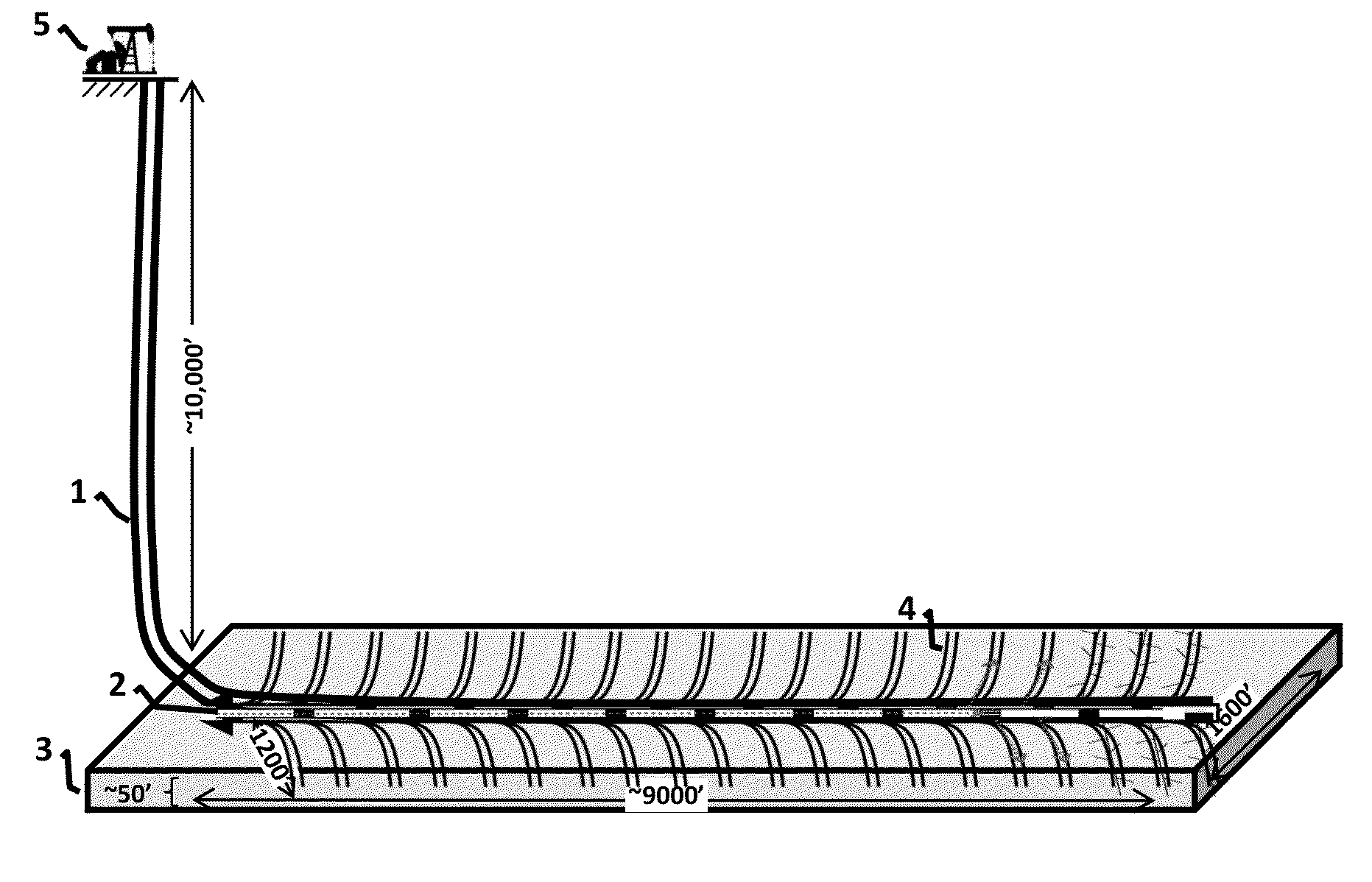
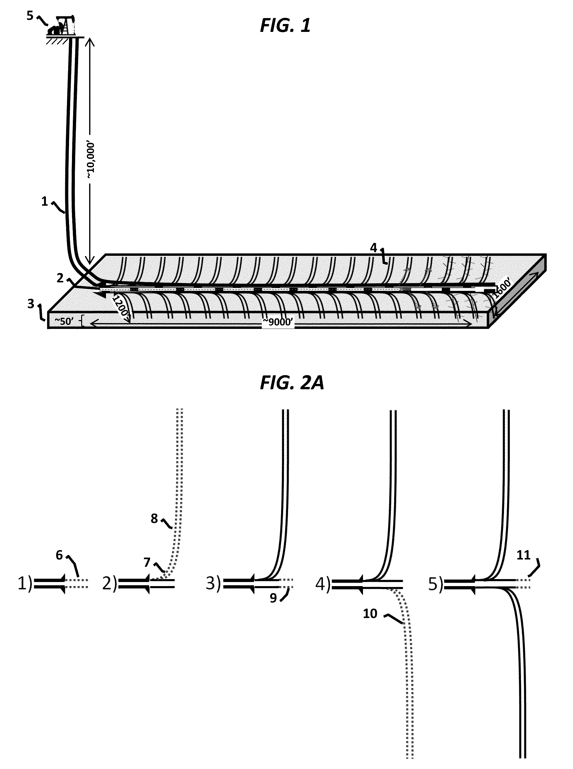
[0015]Referring to FIG. 1 there is shown a well comprising a cased wellbore 1 connecting the surface facilities 5 to the lowest casing shoe 2, below which extends the main horizontal wellbore. The side laterals 4 extend in both directions off the main wellbore. Both the main horizontal wellbore and side laterals are drilled largely within the targeted shale or tight rock zone 3. This figure shows the well during step 2 when the frac string has been run and the fracturing treatments are underway. It depicts the bottom six side laterals as already being fractured, with the next four laterals underway.

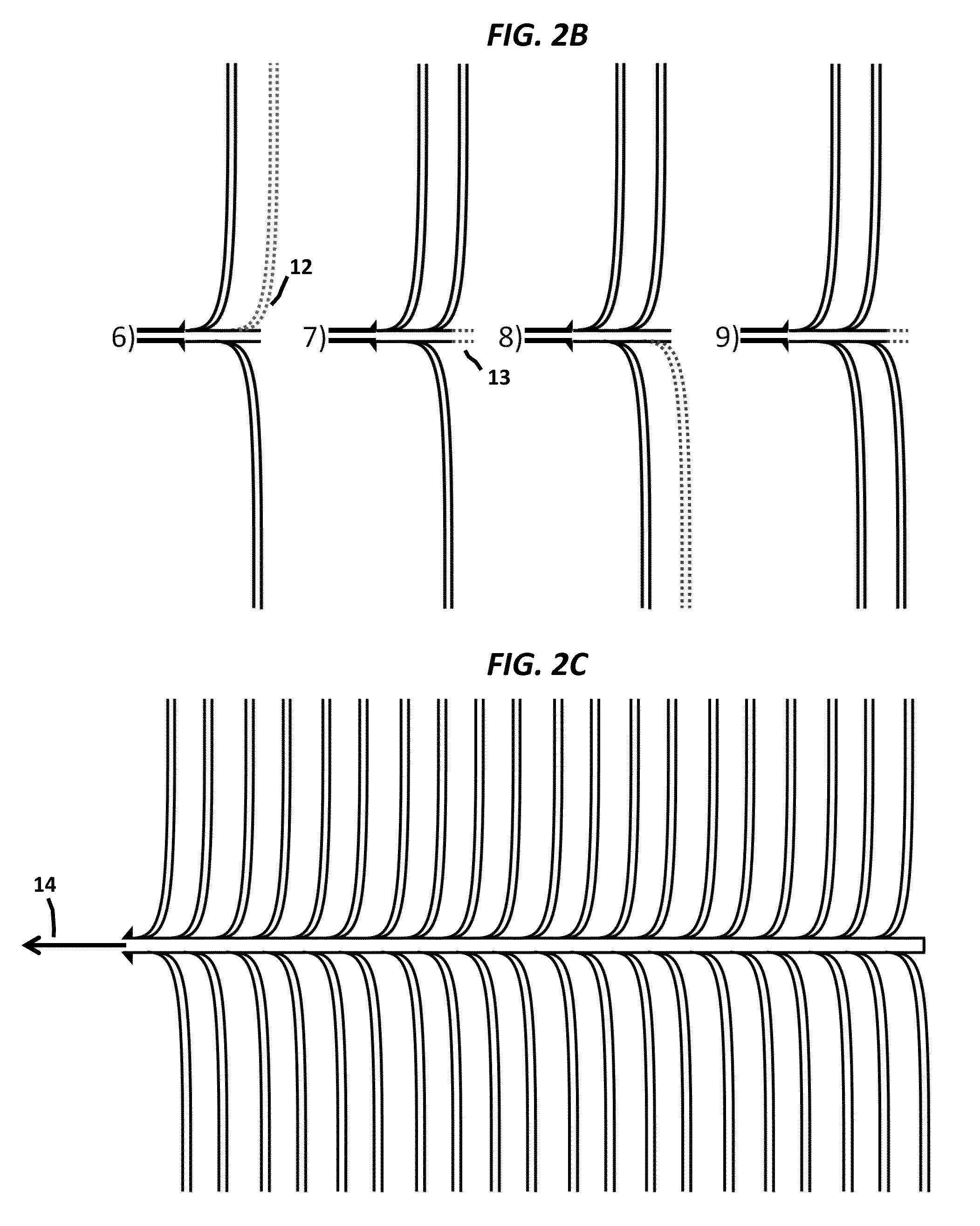
[0016]FIG. 2 shows the construction of the step 1 multilateral well. As shown in FIG. 2A, it begins with drilling a short section 6 out from the casing shoe. Depending on where the casing shoe is landed, this short open hole section may be just a few hundred feet long, or may be longer if the casing shoe is still a further distance from the target zone. The drill assembly is then configur...


PUM


Abstract

A method for developing oil or natural gas shale or tight rock formations by constructing wells in a two step process. The method includes an algorithm for determining under what conditions this two step process is the preferred option for developing a shale or tight rock resource. Step one is to drill a multilateral well with a profusion of unstimulated open-hole laterals from a main wellbore, after which the well is produced for a period of time. Step two is to re-enter the well and install a multistage hydraulic fracture completion. The method includes drilling the main bore and laterals in a specific sequence and geometry to facilitate running a frac liner in the future when the multistage fracturing step is carried out.

Description

TECHNICAL FIELD OF THE INVENTION[0001]The present invention relates generally to the recovery of subterranean resources, and more particularly to a method for enabling commercial production of oil or natural gas from tight rock formations.BACKGROUND OF THE INVENTION[0002]Subterranean deposits of shale or tight rock that contain natural gas or oil are assumed to require hydraulic fracturing during the original drilling in order to create sufficient contact surface area and flow paths to enable production of commercial quantities of hydrocarbons. However, in certain planned or unplanned cases, these same formations have been drilled and put on production before the wells were hydraulically fractured. In some of these cases the wells produced substantial quantities of oil and / or natural gas prior to hydraulic fracturing. These wells already had the expensive equipment installed required for hydraulically fracturing, but the fracturing was delayed for either reservoir evaluation purpose...

Claims


Application Information

Patent Timeline
IPC IPC(8): E21B43/26G06Q50/02G06Q10/06E21B7/06E21B33/124
CPCE21B43/26E21B7/06G06Q50/02G06Q10/0635E21B33/124E21B41/0035E21B43/305
Inventor MALONEY, TIM
Owner ERA EXPLORATION
Learn More