Engine system having coolant control valve

a technology of coolant control valve and engine, which is applied in the direction of multiple way valves, machines/engines, mechanical equipment, etc., can solve the problems of lubricating operation deformation, performance degradation, and exhaust gas quality degradation, so as to simplify the layout of the cooling system, improve the precision of temperature control, and reduce the effect of lubricating operation

Inactive Publication Date: 2016-06-09
HYUNDAI MOTOR CO LTD
View PDF10 Cites 8 Cited by
  • Summary
  • Abstract
  • Description
  • Claims
  • Application Information

AI Technical Summary

Benefits of technology

[0014]Various aspects of the present invention are directed to providing an engine system having a coolant control valve having advantages of appropriately coping with rapid fluctuation in a coolant temperature, enhancing precision of temperature control, and simplifying a layout of a cooling system through a coupling structure of a valve housing and a pump housing.
[0026]According to various embodiments of the present invention, since the coolant control valve is installed in the coolant entrance side of the engine to enhance temperature control precision of a coolant and the coolant control valve and the coolant pump are coupled to be configured as a single module, a layout of the cooling system may be simplified.
[0027]In addition, since the coolant control valve separately cools the cylinder head and the cylinder block and separately controls the coolants circulating in the EGR cooler, the heater core, the oil cooler, and the radiator, overall stability of the cooling system and control efficiency may be enhanced.

Problems solved by technology

When a temperature of the coolant of the engine is low, viscosity of oil may increase to increase frictional force and fuel consumption, and a temperature of an exhaust gas may increase gradually to lengthen a time for a catalyst to be activated which degrades quality of the exhaust gas.
If the temperature of the coolant of the engine is too high, knocking is generated, and adjustment of ignition timing to suppress generation of knocking may degrade performance.
Also, if the temperature of the lubricant is too high, a lubricating operation may be degraded.
The exit control scheme may be vulnerable to rapid fluctuations of coolant temperature, precision of temperature controlling is lowered, and durability of the coolant control valve may be degraded.
In addition, the coolant pump is installed on the coolant entrance side of the engine together with the coolant control valve, and the coolant pump is installed on the coolant entrance side of the engine, resulting in a complicated layout of the cooling system overall.

Method used


Image

  • Engine system having coolant control valve
  • Engine system having coolant control valve
  • Engine system having coolant control valve

Examples


Embodiment Construction

[0035]Reference will now be made in detail to various embodiments of the present invention(s), examples of which are illustrated in the accompanying drawings and described below. While the invention(s) will be described in conjunction with exemplary embodiments, it will be understood that the present description is not intended to limit the invention(s) to those exemplary embodiments. On the contrary, the invention(s) is / are intended to cover not only the exemplary embodiments, but also various alternatives, modifications, equivalents and other embodiments, which may be included within the spirit and scope of the invention as defined by the appended claims.

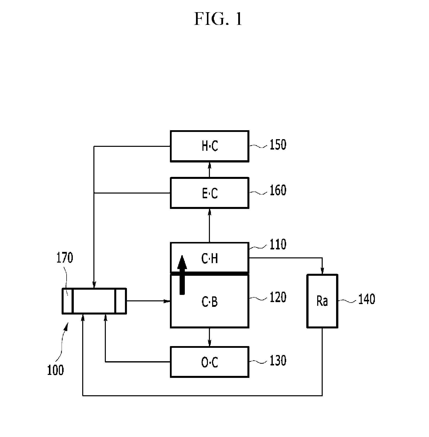
[0036]FIG. 1 is a flowchart illustrating an overall flow of a coolant in an engine system having a coolant control valve according to various embodiments of the present invention.

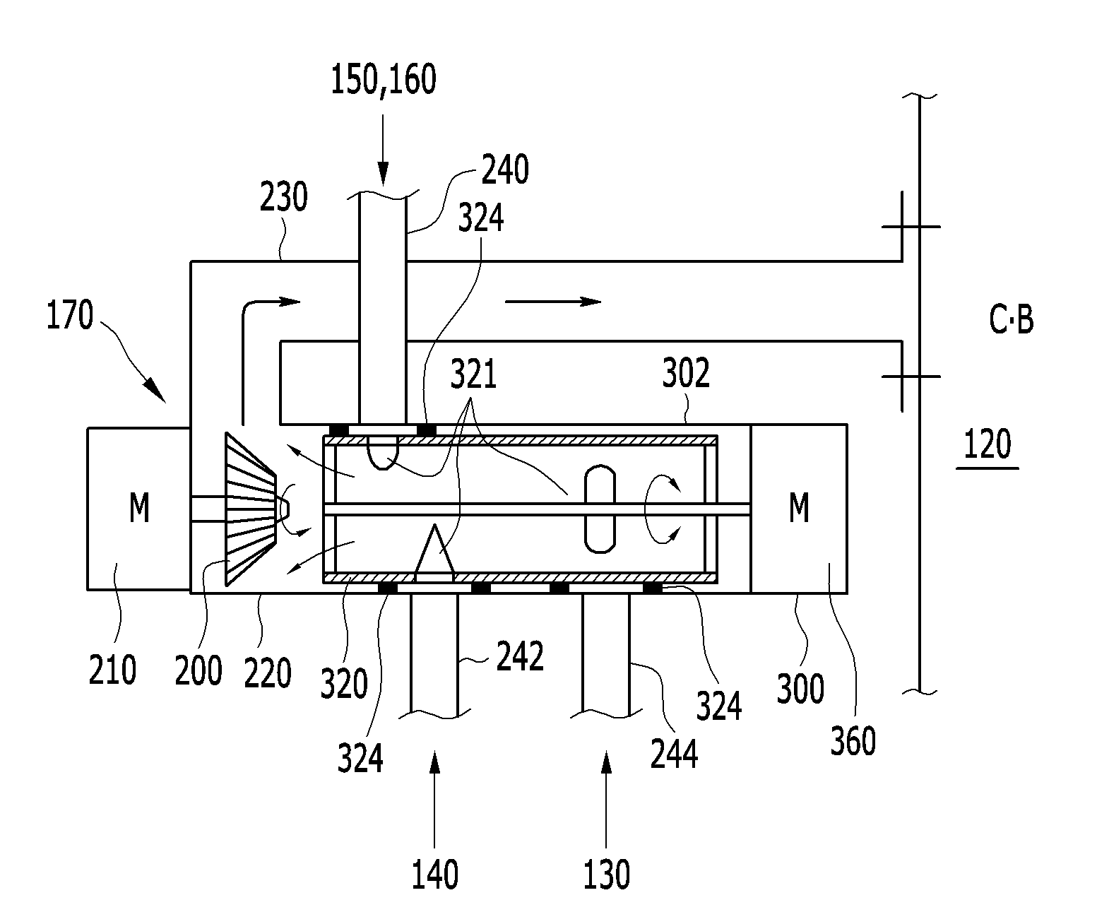
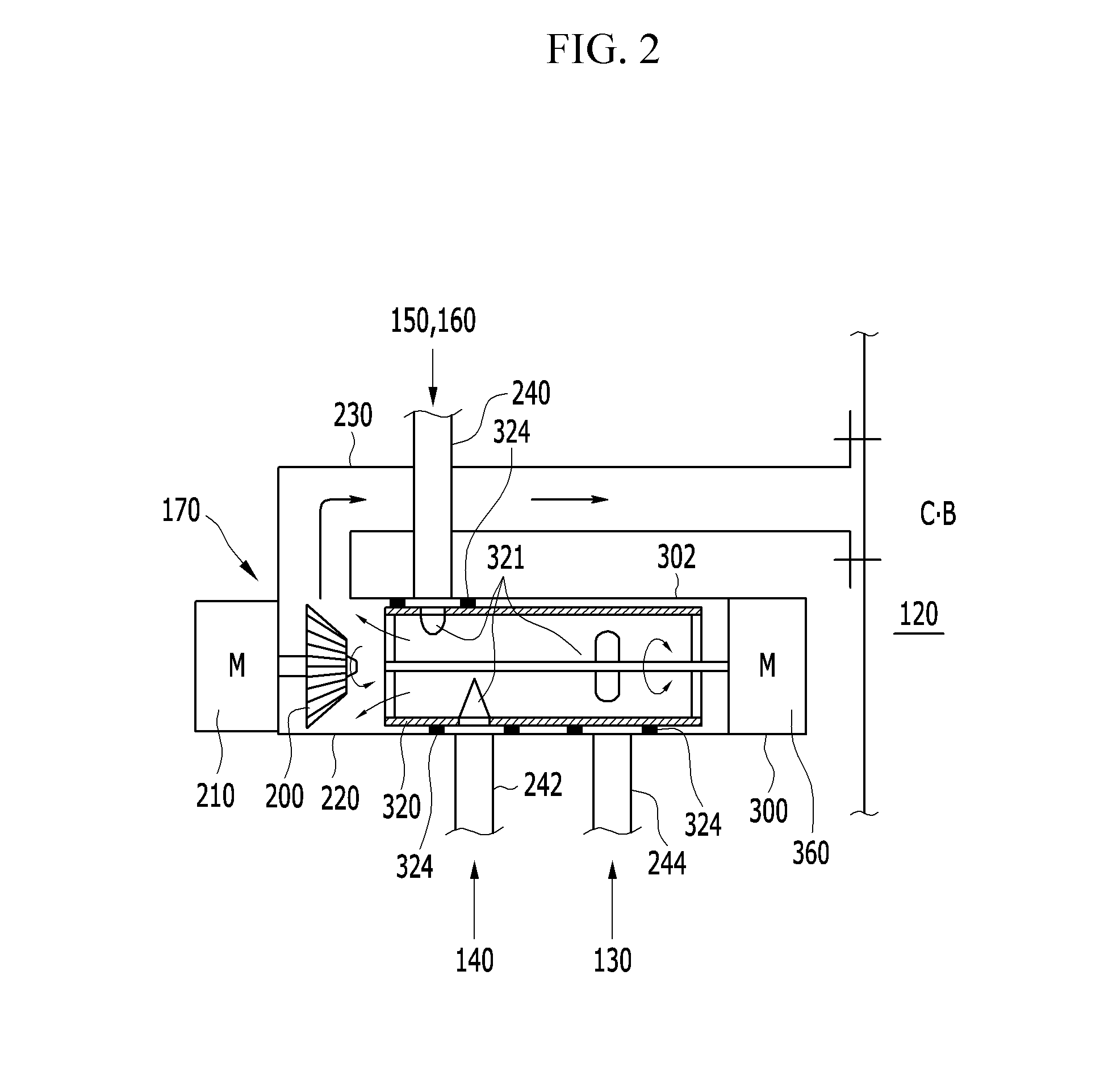
[0037]Referring to FIG. 1, an engine system includes a coolant control valve 100, a cylinder head 110, a cylinder block 120, an oil cooler 130, a radiato...


PUM


Abstract

An engine system having a coolant control valve may include a cylindrical valve having a pipe structure with one side opened and including coolant passages formed in preset positions from one inner circumferential surface to an outer circumferential surface of the cylindrical valve to allow a coolant to pass therethrough, a valve housing configured for the cylindrical valve to be rotatably disposed therein and having connection pipes connected thereto to correspond to the coolant passages, a valve driving device, a pump housing disposed in one end portion of the cylindrical valve to correspond to the opened side of the cylindrical valve, having a pump impeller disposed therein, and coupled to the valve housing, a pump driving device disposed to rotate the pump impeller, and a pump discharge line connected to the pump housing to transmit a coolant pumped by the pump impeller to a cylinder block.

Description

CROSS-REFERENCE TO RELATED APPLICATION[0001]The present application claims priority to Korean Patent Application No. 10-2014-0172136 filed Dec. 3, 2014, the entire contents of which is incorporated herein for all purposes by this reference.BACKGROUND OF THE INVENTION[0002]1. Field of the Invention[0003]The present invention relates to an engine system having a coolant control valve capable of simplifying an overall layout of a cooling system and enhancing control stability of a coolant by disposing the coolant control valve on an entrance side of a coolant of an engine and coupling the coolant control valve and a coolant pump.[0004]2. Description of Related Art[0005]An engine generates rotary power based on combustion of fuel and discharges the remaining energy as thermal energy. In particular, a coolant, while circulating in an engine, a heater, and a radiator, absorbs and discharges the thermal energy.[0006]When a temperature of the coolant of the engine is low, viscosity of oil m...

Claims


Application Information

Patent Timeline
Patent Type & Authority Applications(United States)
IPC IPC(8): F01P7/14F02M26/23F01P11/08F01P5/10F01P3/02
CPCF01P7/14F01P5/10F01P3/02F01P2003/027F02M26/23F01P2007/146F01P11/08F01P7/165F01M5/00F01P3/18F01P7/00F02M26/00F16K11/085Y02T10/12
Inventor LEE, HYO JO
Owner HYUNDAI MOTOR CO LTD
Why Eureka
Try Eureka