Air cannon and associated launch canister for a line-fouling system

a launch canister and air cannon technology, applied in the field of air cannons, can solve the problems of unnecessarily exposed security forces and property (or vips), increased ante, and loss of time, and achieve the effect of reducing the potential damage to a rib and facilitating charging and reloading

Active Publication Date: 2016-06-09
BCB INT
View PDF11 Cites 40 Cited by
  • Summary
  • Abstract
  • Description
  • Claims
  • Application Information

AI Technical Summary

Benefits of technology

[0016]According to a first aspect of the invention there is provided a floating boat fouling line having first and second ends, the floating boat fouling line comprising: a length of high-strength, lightweight cord defining the first and second ends and a central section of the boat fouling line; a first rotating shackle and a second rotating shackle, the first rotating shackle coupled to the first end of the cord and the second rotating shackle coupled to the second end of the cord; at least two drogues each having multiple shroud lines extending from a canopy thereof; wherein the shroud lines from a front drogue are attached to the first rotating shackle and shroud lines from a tail drogue are attached to the second rotating shackle, the rotating shackles both acting as a sink weight to cause, when deployed in water, submersion of each respective canopy and to isolate twisting of the central section of the high-strength cord from twisting of said shroud lines 312 and / or closure of said canopy of each drogue.
[0021]The boat stopping system of the preferred embodiment makes use of a floating line with sea anchor drogues at either end. The drogues are both projected away from an operator of an air cannon by, on the one hand, positive air pressure and, on the other hand, a dragging effect when line extension is reached. The system therefore provides a rapidly deployable boat stopping system having a tactically useful length of prop fouler.
[0031]The air-cannon is capable of being mounted on a RIB since an active recoil mechanism limits force conveyed directly into its mount. The launch canister of the preferred embodiment ensures that a remote end of the prop fouler is projected away from the point of firing to as to ensure that deployment of the prop fouling line occurs under tension and such that a generally straight-line deployment of the prop fouler is achieved. Advantageously, embodiments of the present invention provide a net-launcher that is mechanically optimized in terms of its configuration and number of interacting parts to effect deployment of an effective security cordon / curtain over a large area in a quick, repeatable and safe fashion from a universal gun mount that is not conventionally designed to dissipate recoil.
[0033]Beneficially, the systems and embodiments of the present invention are both easy to charge and reload.
[0034]The amount of pressure generated (especially in the multi-barreled embodiments) may be significant and can simultaneously launch two drag weights over distances of several hundred metres, the drag weights coupled together by a netting that is, typically, up to about two hundred metres across and several metres deep. The resultant security curtain can there act as a propeller-fouler. To mitigate the potential damage to a RIB to which the air cannon is coupled (via a UGM), the air cannon is preferably made from lightweight or composite materials and fitted with an active recoil mechanism.

Problems solved by technology

If this verbally delivered warning is ignored, then time is lost and the ante significantly increased through the threat and use of a lethal response where the navy / coastguard or police enter the fray ‘with all guns blazing’.
With no effective intermediate system and procedure that both keeps the security forces at a reasonably safe distance and maintains the perceived threat at an appropriate remote distance, security forces and property (or VIPs) are unnecessarily exposed to harm and damage.
Another issue arises with mounting, for example, any active device to a RIB.
The UGM is mounted to a fibreglass-hulled RIB, so any recoil through the UGM has the potential to destroy the point of mechanical coupling of the UGM to the RIB.
In the event that the explosive does not ignite or a complex firing mechanism jams, then the system is significantly compromised.
Pyro-based systems therefore have severe limitations, not least because small explosive charges can only accelerate small masses over longer distances and large charges (required for heavy masses) are fundamentally dangerous and require robust, heavily engineered devices to resist the explosive forces.
The device is designed to “capture live game” and its range and power are therefore highly limited.
Furthermore, high speed boats are difficult to stop, especially if it is desired to not damage the boat or occupants during an enforced stop.
However, entangling a propeller (i.e. “prop fouling”) is not easy.
To date, a single line does not work very well as an entanglement device, whilst nets perform relatively well.
However, nets are made up from multiple lines and are consequently heavy and hard to deploy, Nets therefore need either a large launcher or else they have to be kept unacceptably short to be able to be launched from a hand held device.

Method used


Image

  • Air cannon and associated launch canister for a line-fouling system
  • Air cannon and associated launch canister for a line-fouling system
  • Air cannon and associated launch canister for a line-fouling system

Examples


Embodiment Construction

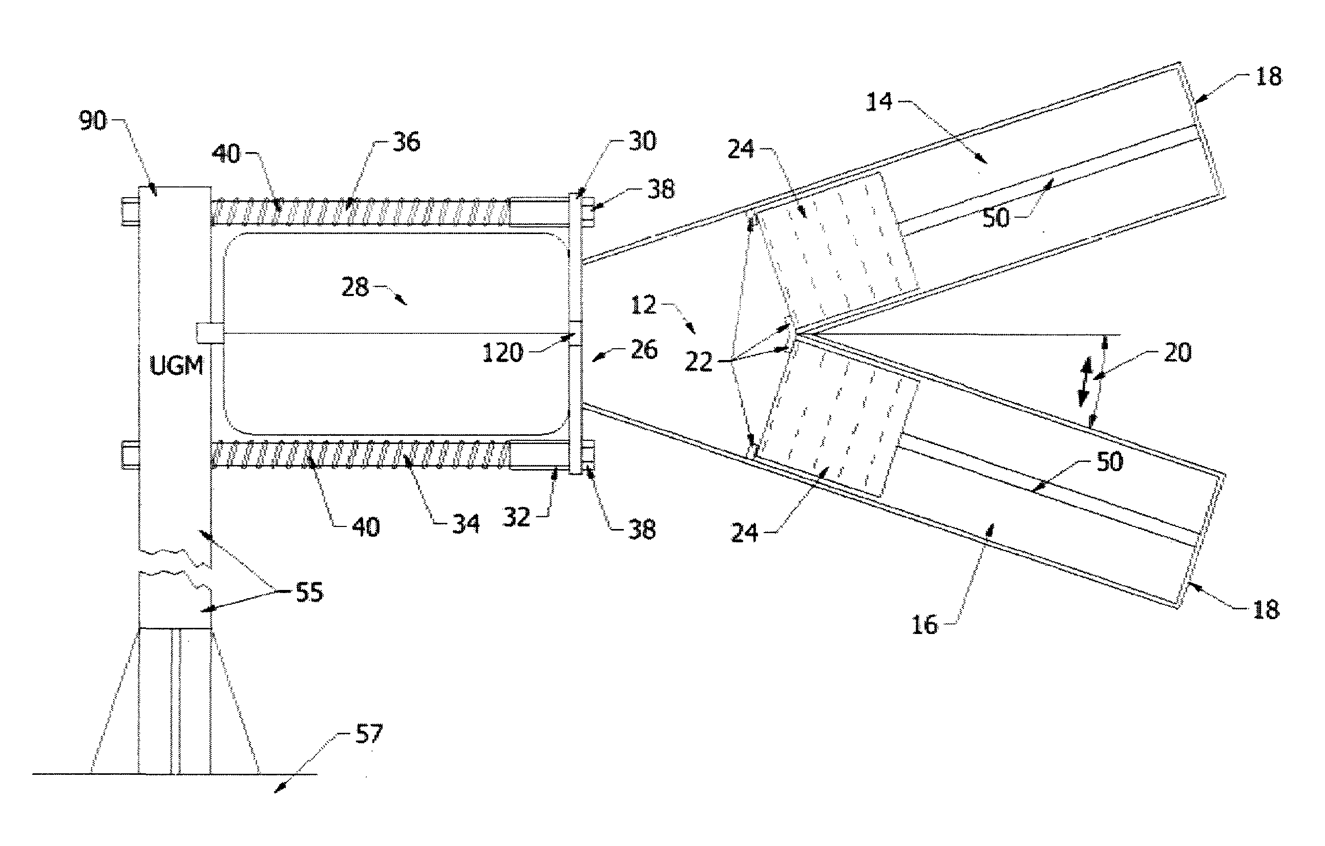
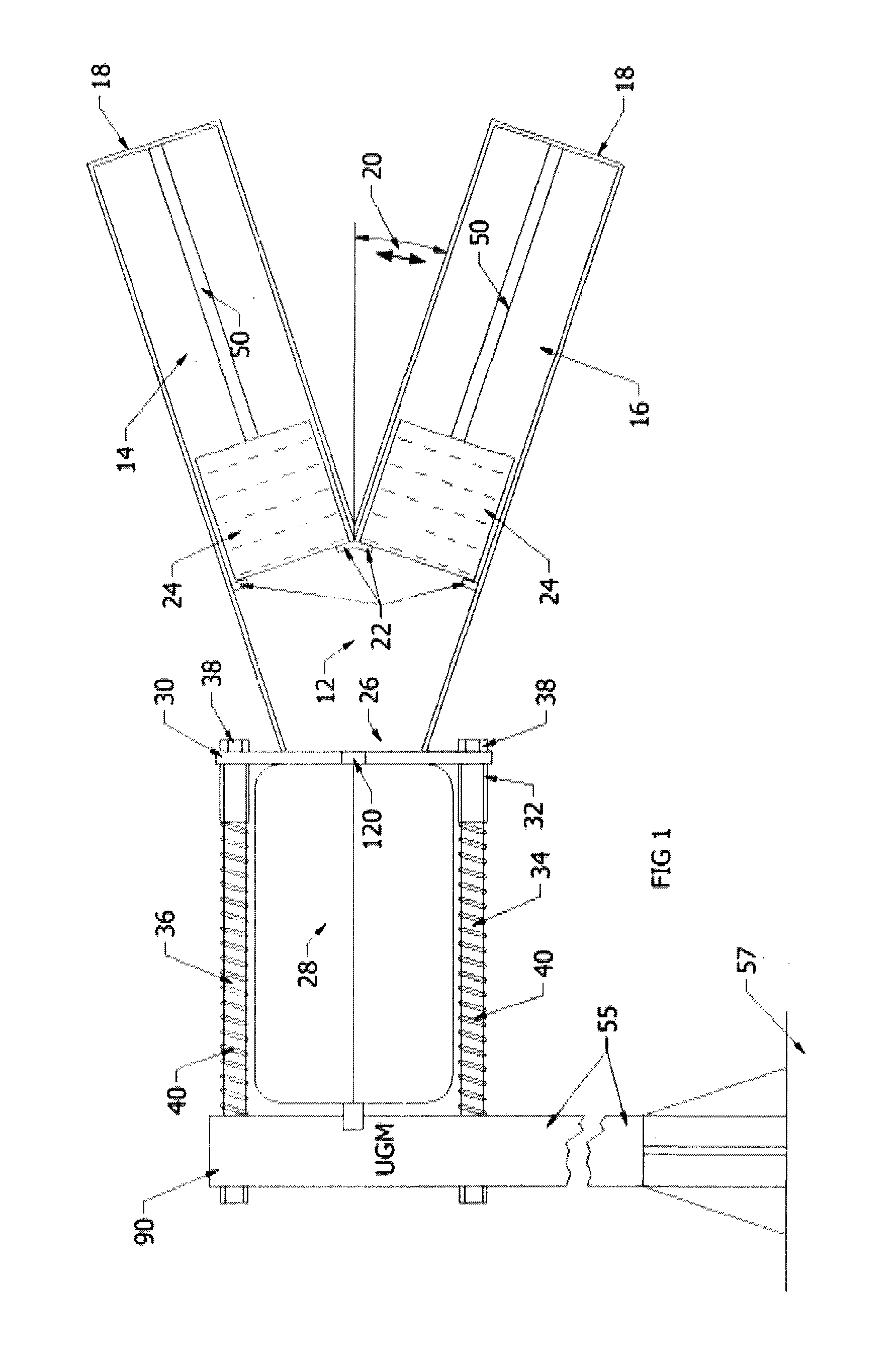
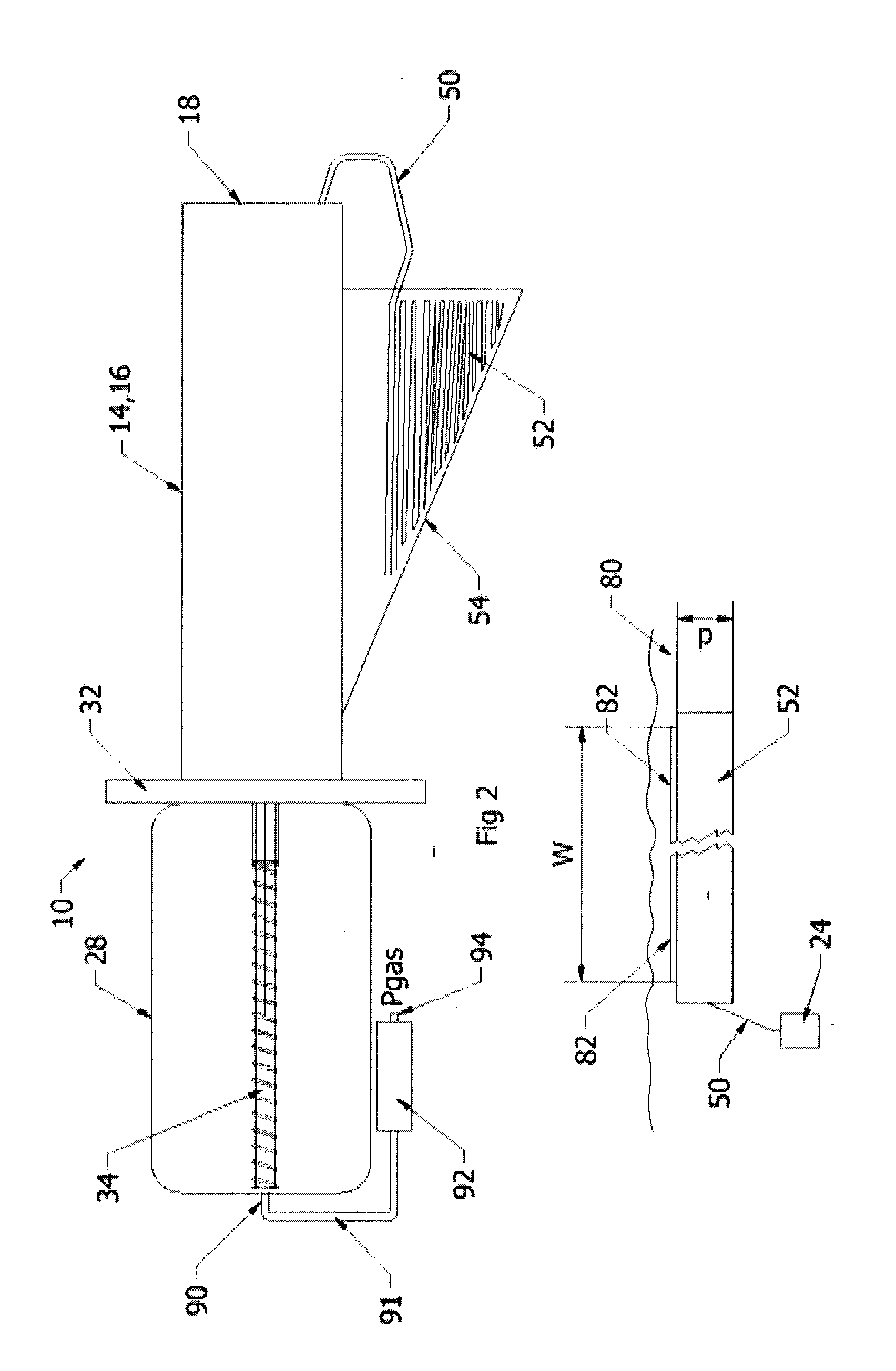
[0046]With reference to FIGS. 1 and 2 of the drawings, there is shown a schematic representation of a multi-barrelled air cannon 10 of a preferred embodiment of the present invention.

[0047]In a preferred embodiment, a breech chamber 12 (which essentially is an air expansion manifold) is bifurcated into identical first and second barrels 14, 16 each having a muzzle end 18. Relative to a nominal centre line 20 through a major axis of the multi-barrelled air cannon 10 that centrally dissects the breech chamber 12, the angular offset a of each of the first and second channels is typically in the region of between about five degrees and ten degrees and preferably about eight degrees. The volume of the breech chamber is made as small as possible in order to channel energy from the expanding volume into the barrels 14, 16.

[0048]Conventionally, the barrels 14, 16 have a generally circular cross section. The barrels 14, 16 are typically of a similar overall length to the length of the breech...


PUM

PropertyMeasurementUnit
volumeaaaaaaaaaa
volumeaaaaaaaaaa
weightaaaaaaaaaa

Abstract

FIG. 7 shows an air cannon system loaded with a launch canister containing a prop-fouler. A pressure vessel (28) contains an inlet including a poppet valve (100) that, upon command, can be selectively placed in either a one-way flow position to permit charging of the pressure vessel or otherwise opened to trigger rapid discharge through pressure equalization with the ambient environment. The air cannon may include multiple splayed barrels or a single barrel (158). A launch canister (202), realized in the form of a tube, has a driving plate (350) that closes an end of the launch tube. The driving plate is the first point loaded into the barrel. Within the launch canister (202) a first portion of a floating prop-fouling line is stored. The prop-fouling line, such as made from Dyneema®, has at its ends two drogues that, upon entry into the water, fill with water to produce drag resistance to movement of the prop-fouling line. To avoid undue stress on canopy panels of each drogue and to avoid twisting of shroud lines (312) to the canopy, a rotating shackle (310a, 310b) acts as a coupling point between the shroud lines (312) and the prop-fouling line. Only one drogue (306), its associated coupling and a selected length prop-fouling line are loaded into the launch canister, with the other drogue and its rotating shackle (310b) loaded into a cradle (166). Upon firing, gas expansion causes the rapid acceleration and ejection of the launch tube (202) and generally straight line deployment of the prop-fouling line (302).

Description

BACKGROUND TO THE INVENTION[0001]This invention relates, in general, to an air cannons and is particularly, but not exclusively, applicable to air cannons in combination with a launch canisterthataids in deployment of a security cord or net (commonly referred to as a “prop-fouler”) as a near-surface, floating security curtain.SUMMARY OF THE PRIOR ART[0002]With respect to the security policing of jetties, ships or more generally waterways, there is currently a two-level approach to fending off potential threats or active incursions launched from boats, dingys and the like. As an initial approach to a perceived boat-based threat, the security force (typically on a RIB or on-shore) shout a warning “to cease activity and move away”. If this verbally delivered warning is ignored, then time is lost and the ante significantly increased through the threat and use of a lethal response where the navy / coastguard or police enter the fray ‘with all guns blazing’. With no effective intermediate s...

Claims


Application Information

Patent Timeline
Patent Type & Authority Applications(United States)
IPC IPC(8): F41H13/00B63B21/48B63B21/22F41F1/08
CPCF41H13/0006B63B21/22B63B21/48F41F1/08A63B71/0036F41H11/05A63B2071/025F41B11/62A61K38/162B63C9/26G06F11/3419G06F11/3438A63B69/224
Inventor SEARLEHOCKING, WILLIAM MARKHOWELL, ANDREW RHYSTAYLOR, DEREK WILLIAM
Owner BCB INT
Why Eureka
Try Eureka