
Electronic timepiece

a technology of electronic timepieces and planar antennae, which is applied in the direction of electric winding, instruments, and horology, etc., can solve the problems of limited size of planar antennae used in small electronic timepieces such as wristwatches, and the thickness of electronic timepieces

Active Publication Date: 2016-06-09
SEIKO EPSON CORP
View PDF1 Cites 16 Cited by
  • Summary
  • Abstract
  • Description
  • Claims
  • Application Information

AI Technical Summary

Benefits of technology

The patent describes a way to make a small electronic timepiece by placing the antenna, motor, and battery in a way that reduces the size of the timepiece. By having a subdial that doesn't overlap with the planar antenna, metal parts can be used for the markers on the subdial, improving the design of the timepiece.

Problems solved by technology

This increases the thickness of the electronic timepiece.
Planar antennae used in small electronic timepieces such as wristwatches are limited in size, however, and therefore generally use a dielectric to achieve a wavelength shortening effect.

Method used


Image

  • Electronic timepiece
  • Electronic timepiece
  • Electronic timepiece

Examples


embodiment 1

[0055]A first embodiment of the invention is described below. Note that the crystal 31 side of the electronic timepiece 1 according to this embodiment of the invention is also referred to as the face, front, or top side, and the back cover 12 side is also referred to as the back or bottom side of the electronic timepiece 1.

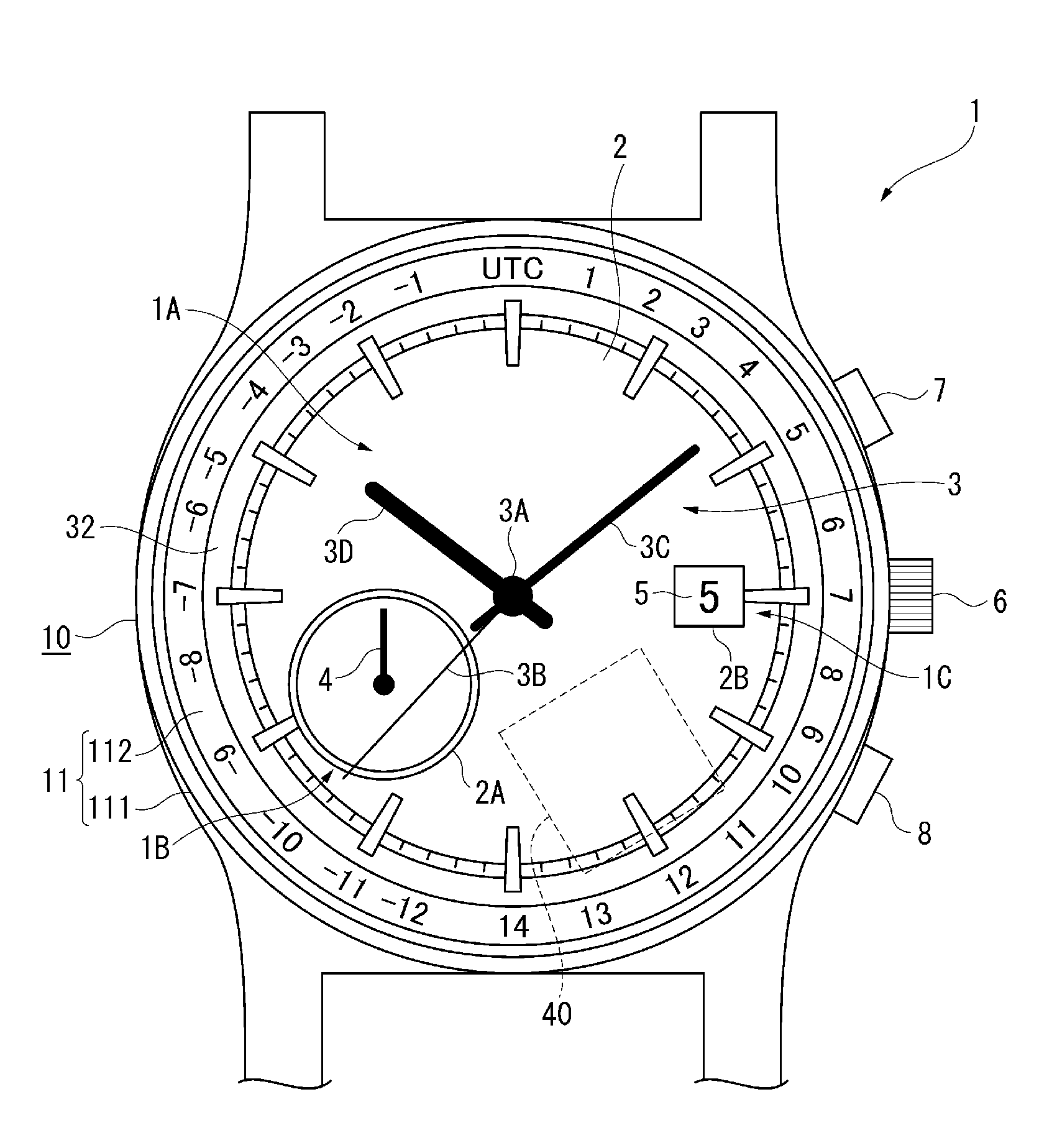
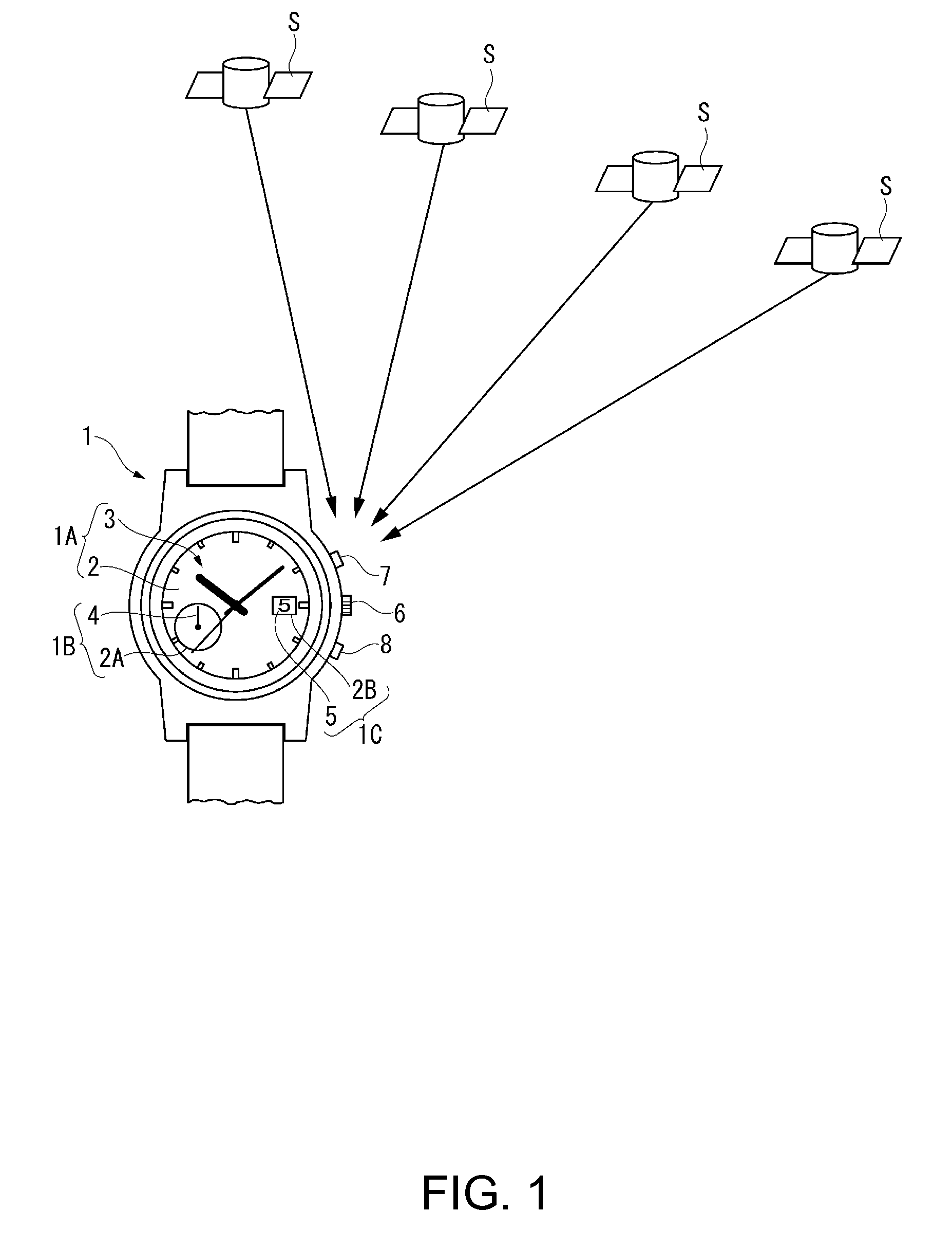
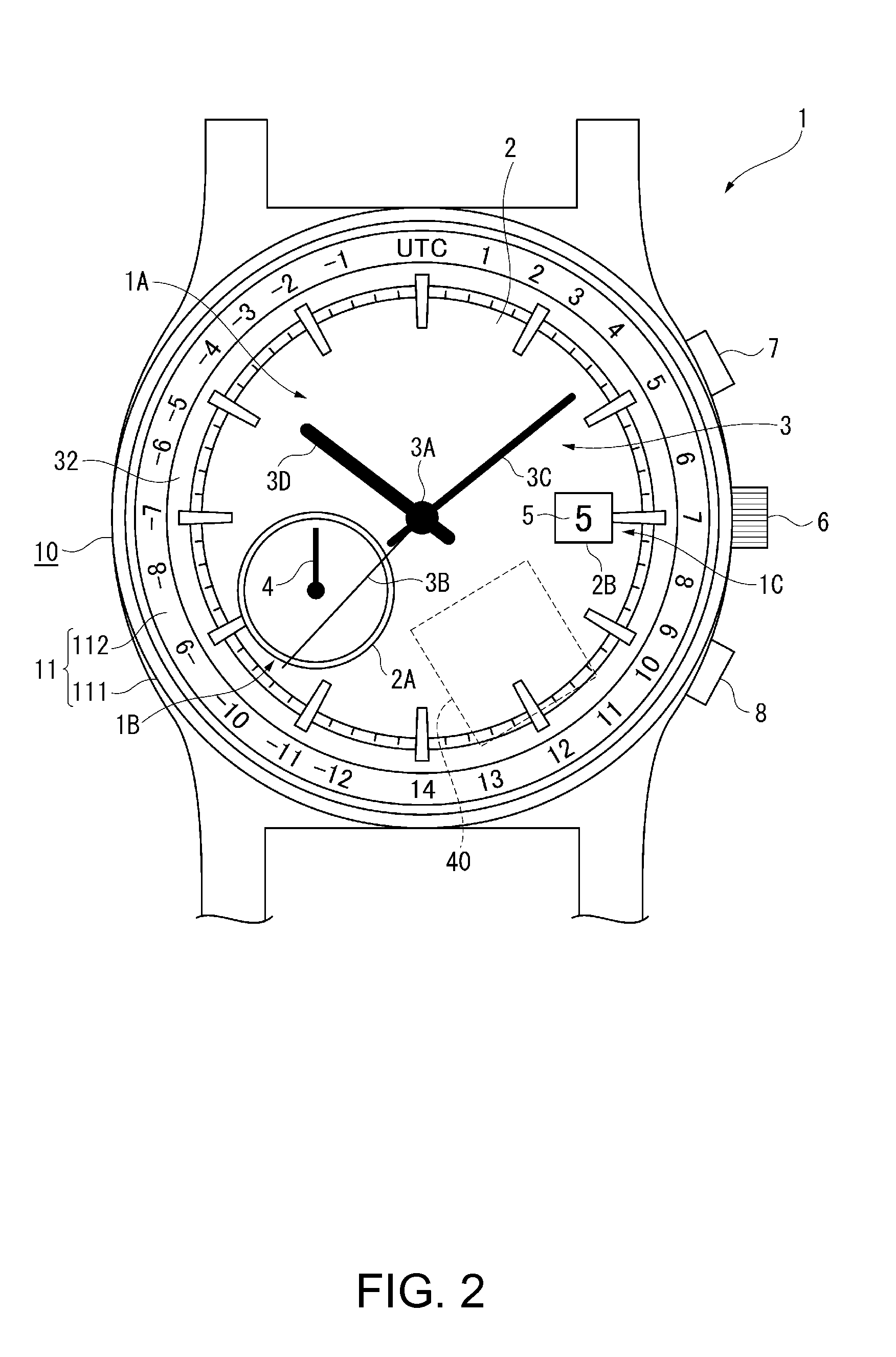
[0056]As shown in FIG. 1 and FIG. 2, the electronic timepiece 1 is a wristwatch with a time display unit 1A for displaying the time using a dial 2 and hands 3, an information display unit 1B including a subdial 2A of the dial 2 and a hand 4, and a calendar display unit 1C including a window 2B in the dial 2 and a date wheel 5.

[0057]The dial 2 is a disc-shaped member made of polycarbonate or other non-conductive material. The subdial 2A is located at 8:00 on the dial 2, and the window 2B is located at 3:00 on the dial 2. In addition to the subdial 2A and window 2B, the dial 2 has a through-hole 2C through which the center pivot 3A of the hands 3 passes, and a throu...

embodiment 2

[0161]A second embodiment of the invention is described next with reference to FIG. 10 to FIG. 12. Note that like parts in the second embodiment and the first embodiment are identified by like reference numerals, and further description thereof is omitted.

[0162]The electronic timepiece 100 according to the second embodiment of the invention differs from the first embodiment in that the number of stepper motors and the number of pivots are greater than in the first embodiment, and by using a storage battery 24A with a small planar size, the storage battery 24A is disposed to a position not overlapping the stepper motors 221 to 224, the planar antenna 40, or the wheel trains 225, 227, and 228 in plan view.

[0163]As shown in FIG. 11, the second embodiment has a pivot 9A disposed at a different planar position than pivot 3A and pivot 4A, and a fifth stepper motor 229 that drives the pivot 9A is added.

[0164]More specifically, the first stepper motor 221 and first wheel train 225 that driv...


PUM


Abstract

An electronic timepiece has a time display unit including a dial made from a non-conductive material, and hands; and a movement that drives the hands. The movement includes a circuit board, a planar antenna attached to the circuit board, a stepper motor that drives the hands, and a battery. The planar antenna, the stepper motor, and the battery are disposed to positions overlapping the time display unit in plan view, and not overlapping each other in plan view.

Description

BACKGROUND[0001]1. Technical Field[0002]The present invention relates to an electronic timepiece, and relates more particularly to an electronic timepiece with a planar antenna.[0003]2. Related Art[0004]JP-A-2012-13627 describes an electronic timepiece with a planar antenna for receiving radio frequency signals transmitted from GPS (Global Positioning System) or other types of positioning information satellites.[0005]The electronic timepiece in JP-A-2012-13627 has a planar antenna disposed on the back cover side of the dial, and suppresses loss of antenna sensitivity by separating the planar antenna from the metal case around the antenna.[0006]In the electronic timepiece taught in JP-A-2012-13627, the planar antenna and the battery are disposed overlapping in plan view with the circuit board therebetween. This increases the thickness of the electronic timepiece. Planar antennae used in small electronic timepieces such as wristwatches are limited in size, however, and therefore gener...

Claims


Application Information

Patent Timeline
IPC IPC(8): G04G17/04G04G17/02G04R20/02G04R60/10
CPCG04G17/04G04R20/02G04G17/02G04R60/10G04C10/02G04R60/12
Inventor FUJISAWA, TERUHIKOTAMURA, SHUICHI
Owner SEIKO EPSON CORP
Learn More