Image pick-up window defogging function-equipped built-in camera hand piece

a built-in camera and image pickup technology, which is applied in the field of image pickup window defogging function-equipped built-in camera hand pieces, can solve the problems of difficult to obtain clear video images of the affected area and the surrounding region thereof by using a video camera, and achieve the effect of preventing the adhesion of cutting waste or water droplets, preventing the adhesion of cutting waste or

Inactive Publication Date: 2016-06-16
YOSHIDA DENTAL MFG
View PDF5 Cites 6 Cited by
  • Summary
  • Abstract
  • Description
  • Claims
  • Application Information

AI Technical Summary

Benefits of technology

[0009]According to the present invention of claim 1, in a hand piece equipped with a head part on the distal end side with a cutting tool for treating an affected area detachably mounted on the head part like a hand piece such as an air turbine, an ultrasonic scaler, or the like, an air flow from the defogging air flow path mechanism prevents the adhesion of cutting waste or water droplets generated during a cutting work in the affected area to the outer surface of the image pick-up window to defog the image pick-up window, thereby enabling the provision of an image pick-up window defogging function-equipped built-in camera hand piece capable of picking up a clear color image by guiding light from the image pick-up window through an image pick-up optical system to the camera.
[0010]According to the present invention of claim 2, in a hand piece including: a hand piece body having a grip part equipped with a head part on the distal end side with a cutting tool for treating an affected area detachably mounted on the head part and having one coupling part at the rear end of the grip part; and a dental tube part having the other coupling part detachably mounted on the hand piece body, like a hand piece such as an air turbine, an air motor, a micromotor, or the like, an air flow from the defogging air flow path mechanism prevents the adhesion of cutting waste or water droplets generated during a cutting work in the affected area to the outer surface of the image pick-up window to defog the image pick-up window, thereby enabling the provision of an image pick-up window defogging function-equipped built-in camera hand piece capable of picking up a clear color image by guiding light from the image pick-up window through the image pick-up optical system to the camera.
[0011]According to the present invention of claim 3, in an air turbine hand piece, an air flow from the defogging air flow path mechanism prevents the adhesion of cutting waste or water droplets generated during a cutting work in the affected area to the outer surface of the image pick-up window to defog the image pick-up window, thereby enabling the provision of an image pick-up window defogging function-equipped. built-in camera hand piece capable of p...

Problems solved by technology

In the case of the dental hand piece device in Patent Document 1, however, cutting waste or the like generated during treatment of the affected area with a cutting tool adheres to the observation aperture in the surroundings of the tool mounting part, while the dental hand piece device does not have a defogging function for preventing the fog...

Method used


Image

  • Image pick-up window defogging function-equipped built-in camera hand piece
  • Image pick-up window defogging function-equipped built-in camera hand piece
  • Image pick-up window defogging function-equipped built-in camera hand piece

Examples


embodiments

[0039]Hereinafter, an image pick-up window defogging function-equipped built-in camera hand piece (hereinafter, referred to as “built-in camera hand piece”) according to embodiments of the present invention will be described with reference to accompanying drawings.

first embodiment

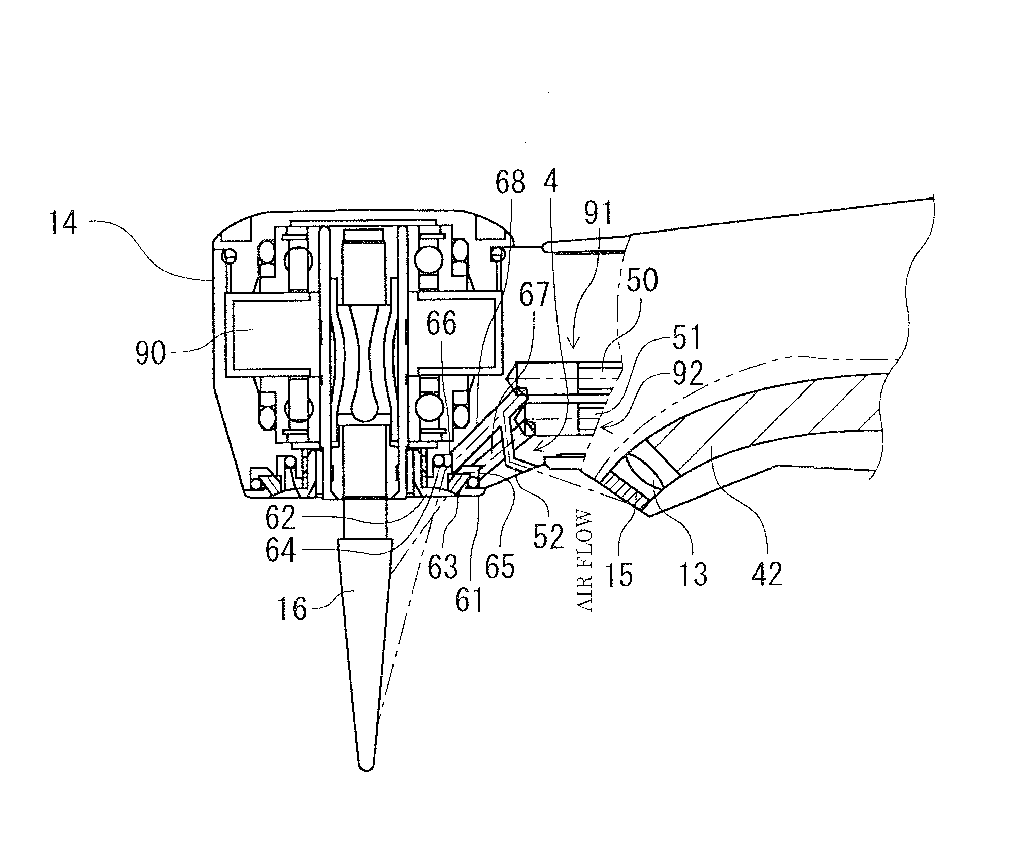
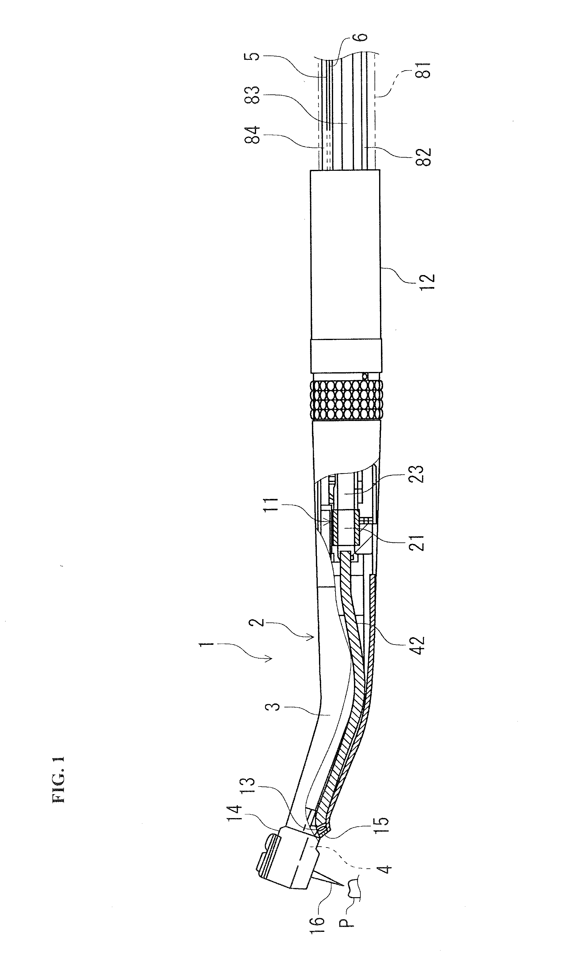
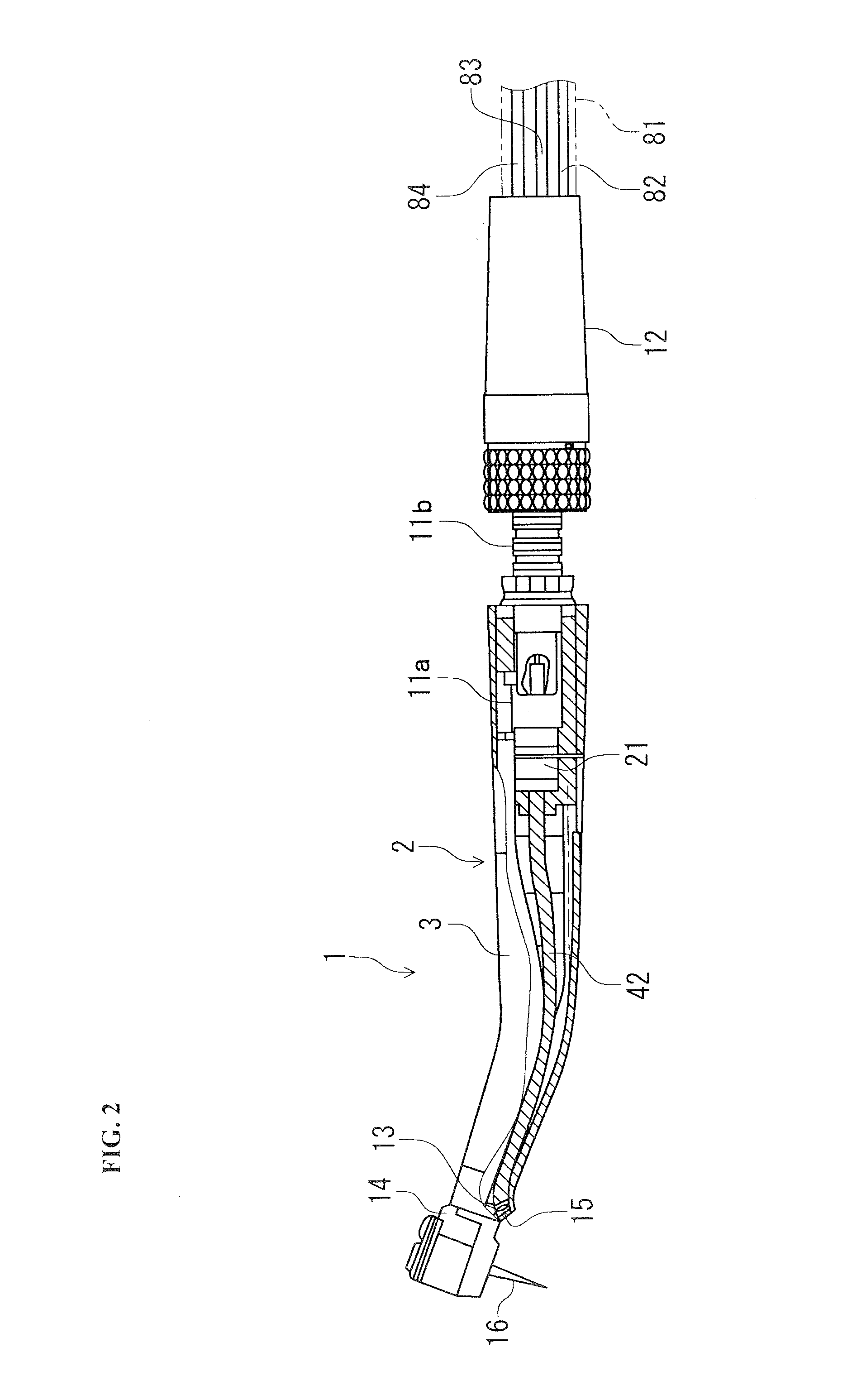
[0040]A built-in camera hand piece 1 of the first embodiment will be described with reference to FIGS. 1 to 16.

[0041]The built-in camera hand piece 1 of the first embodiment is configured to be of, for example, an air-turbine-driven type as illustrated in FIGS. 1 to 4 and includes: a hand piece body 2 equipped with a head part 14, on which a cutting tool 16 for treating an affected area P is detachably mounted, on the distal end side and including a grip part 3 equipped with a coupling part 11a inside on the rear end side; and a dental tube part 12 equipped with a coupling part 11b attachable / detachable to / from the coupling part 11a of the grip part 3. The coupling part 11a (on the hand piece body 2 side) and the coupling part lib (on the dental tube part 12 side) constitute the coupling part 11.

[0042]In the built-in camera hand piece 1, the coupling parts 11a and 11b are configured to be rotatably and detachably coupled to each other in a coaxial arrangement by bearing coupling as ...

second embodiment

[0090]Subsequently, a built-in camera hand piece 1C according to a second embodiment of the present invention will be described with reference to FIGS. 17 and 18.

[0091]Although the entire configuration of the built-in camera hand piece 1C according to the second embodiment is substantially the same as that of the built-in camera hand piece 1 of the first embodiment and the defogging air flow path mechanism 4 is the same as in the first embodiment, the built-in camera hand, piece 1C is characterized by that the rod fiber 42 is omitted and the color camera module 21 is arranged in the inside of the grip part 3 and in the inside of the objective lens 13 as schematically illustrated in FIGS. 17 and 18.

[0092]Further, although a detailed wiring structure is omitted, the built-in camera hand piece 1C is characterized by that a camera cable 23 connected to the color camera module 21 is guided into the dental tube part 12 passing through the inside of the grip part 3 and of the coupling part...


PUM


Abstract

The present invention provides an image pick-up window defogging function-equipped built-in camera hand piece having a function of treating an affected area and an image observation function of observing the affected area or the like with a camera and capable of defogging the outer surface of an image pick-up window by preventing adhesion of cutting waste and water droplets to the image pick-up window. An image pick-up window defogging function-equipped built-in camera hand piece 1 of the present invention is provided with a defogging air flow path mechanism 4 in a surrounding position of an image pick-up window 15 arranged facing a cutting site of a cutting tool 16, wherein the defogging air flow path mechanism 4 branches from the air flow path system 91 and injects an air flow within a region from the outer surface of the image pick-up window 15 to the cutting site of the cutting tool 16 to shield an area between the outer surface of the image pick-up window 15 and the cutting site by the air flow to defog the outer surface of the image pick-up window 15.

Description

TECHNICAL FIELD[0001]The present invention relates to an image pick-up window defogging function-equipped built-in camera hand piece and more particularly to an image pick-up window defogging function-equipped built-in camera hand piece having a function of treating an affected area, and a function of observing the affected area and surrounding region thereof by using a camera image and capable of defogging the image pick-up window for the camera.BACKGROUND ART[0002]In the field of dental treatment, a practitioner treats an affected area (treatment site) such as a carious tooth or the like in the oral cavity by frequently using a cutting hand piece for cutting and removing a dentine part of the affected area while visually observing the treatment site.[0003]Furthermore, in recent years, there has been developed a dental hand piece having an image photographing function for intraoral observation in addition to the treatment function.[0004]For example, Patent Document 1 proposes a den...

Claims


Application Information

Patent Timeline
IPC IPC(8): A61B1/253A61B1/05
CPCA61B1/253A61B1/05A61C1/08A61C3/02A61B1/00087A61B2090/3614A61B2090/306A61C1/05A61C1/052A61C1/088
Inventor YAMANAKA, MICHIZOHASEGAWA, TAKESHI
Owner YOSHIDA DENTAL MFG
Why Eureka
Try Eureka