Cardiac Valve Repair Device

Active Publication Date: 2016-06-16
SUZHOU INNOMED MEDICAL DEVICE
View PDF5 Cites 45 Cited by
  • Summary
  • Abstract
  • Description
  • Claims
  • Application Information

AI Technical Summary

Benefits of technology

[0016]In addition to the objects set forth above, the present invention provides a cardiac valve repair device that can be suspended within the flow path o

Problems solved by technology

Congenital, inflammatory, infectious conditions or diseases may lead to dysfunction of the valves over time.
Such degradation may result in serious cardiovascular compromise or even death.
The mitral valve and the aortic valve which are subjected to the systemic circulation high pressure generated by the left ventricle are more susceptible to dysfunction, such as stenosis or regurgitation.
For example, a stenotic mitral valve may impede blood flow into the heart, causing blood to back up and pressure to build in the lungs.
Regurgitation occurs when the mitral valve leaflets do not coapt correctly, thus causing blood to leak backwards into the left atrium and lungs each time the heart pumps.
Although the heart may gradually compensate for this overload as the leakage progresses slowly through months and years, the heart will eventually begin to fail.
All current valve prostheses have disadvantages, such as need for long-term maintenance with blood thinners, the risk

Method used


Image

  • Cardiac Valve Repair Device
  • Cardiac Valve Repair Device
  • Cardiac Valve Repair Device

Examples


Embodiment Construction

[0035]The following detailed description is of the best presently contemplated modes of carrying out the invention. This description is not to be taken in a limiting sense, but is made merely for the purpose of illustrating general principles of the invention. The scope of the invention is best defined by the appended claims.

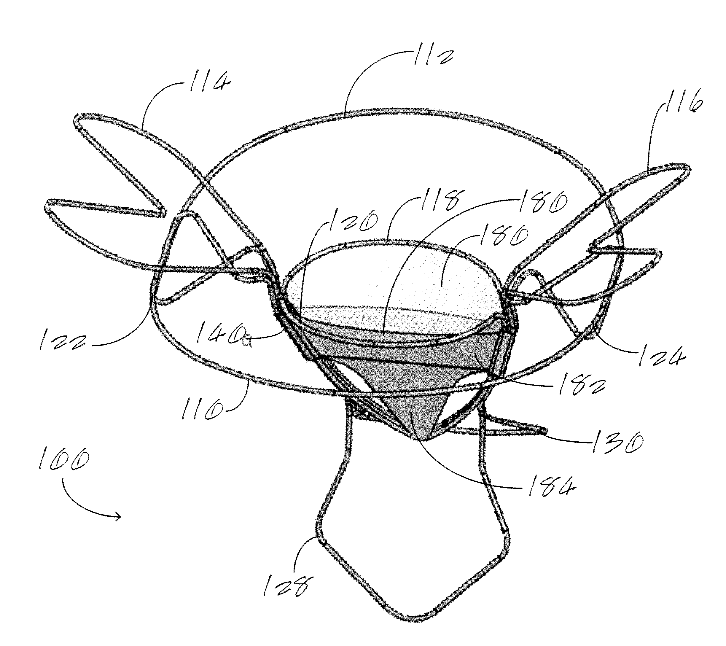
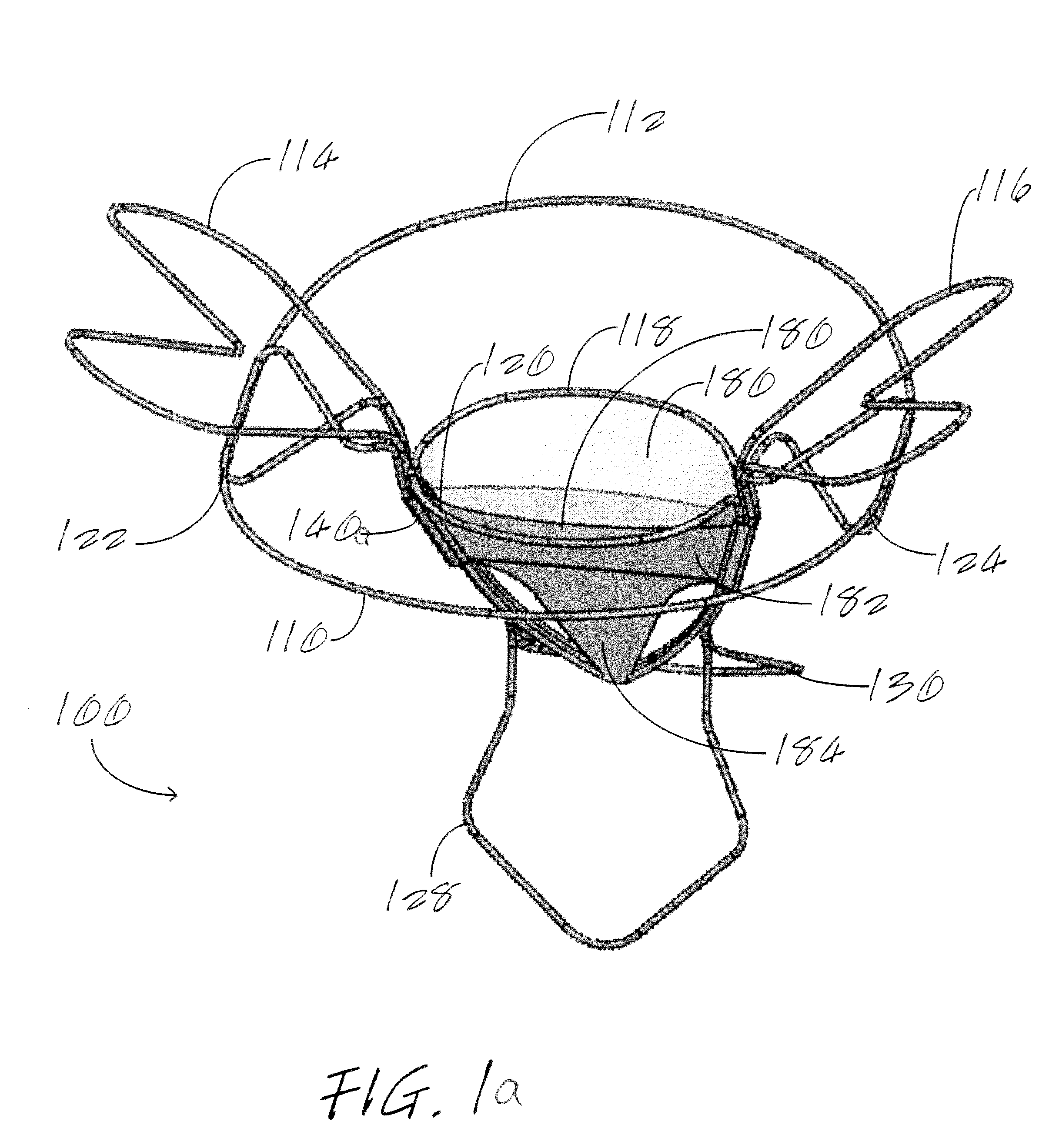
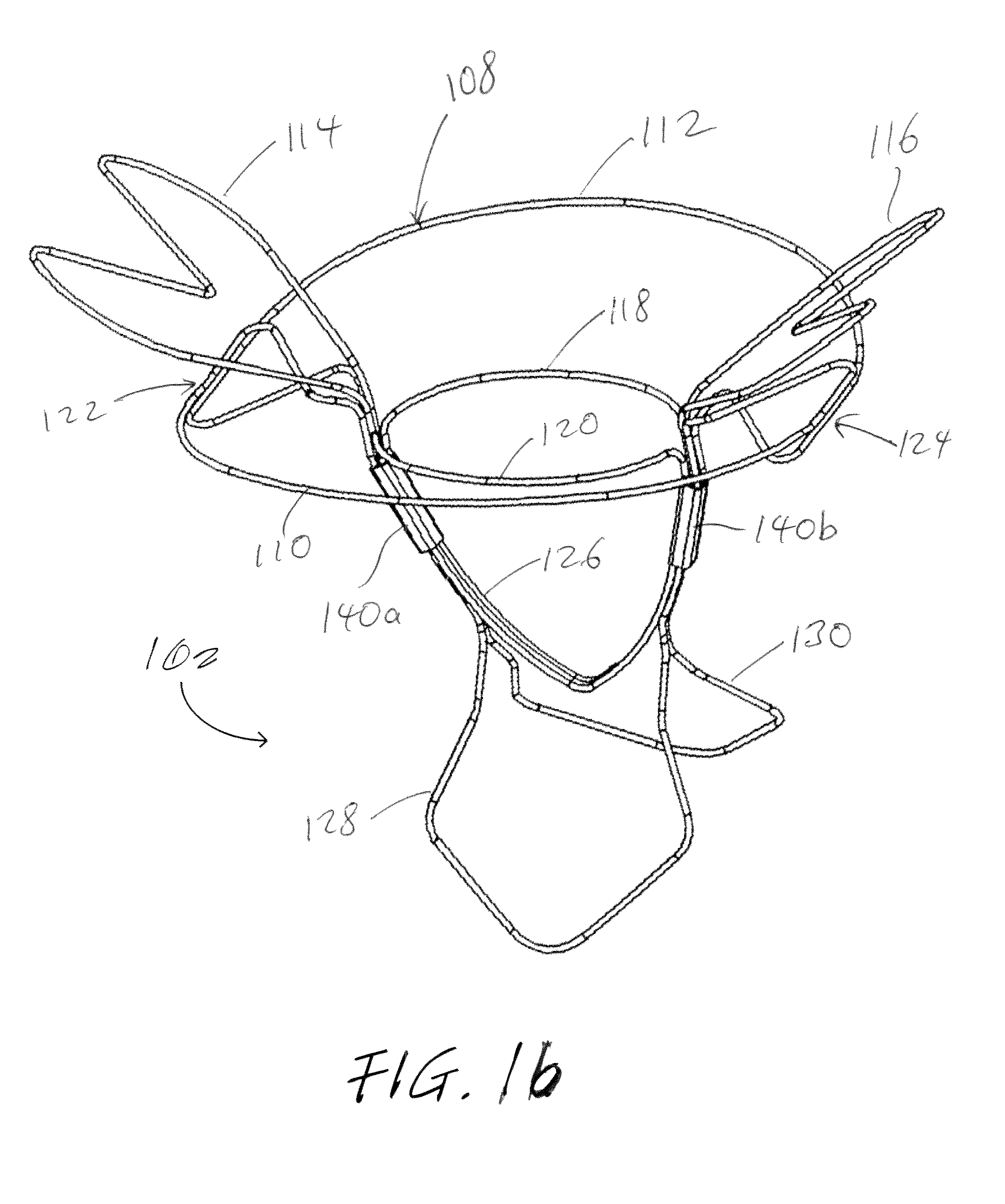
[0036]As shown in FIGS. 1a and 1b, the cardiac valve repair device 100 of the present invention has the following two main structural components: a support frame assembly 102 and a membrane assembly 104. The membrane assembly 104 comprises a plurality of membranes which can be constructed from either synthetic material (e.g., PTFE) or biological material (e.g., pericardium). They serve as outer covering membranes positioned above the native mitral valve's anterior and posterior leaflets, and function to prevent mitral valve leaflet prolapse. They come into contact with the native mitral valve leaflet's free margin and leaflet surface, both of which form the valv...


PUM


Abstract

A cardiac valve repair device has a membrane assembly and a frame. The frame has a central structure that defines a central separation, a pair of sleeves positioned below the central structure, and a pair of atrial alignment expansion beams. Each atrial alignment expansion beam has a curved section and inner section at each opposite end that defines a scissor-crossing where they overlap each other to form a separate lower expansion clip beam at each of the opposite ends thereof. The cardiac valve repair device also includes a pair of upper expansion clip beams. A V-shaped ventricular expansion curved beam extends below the two sleeves, with the membrane assembly secured to the V-shaped ventricular expansion curved beam. A pair of ventricular alignment stabilizing beams extends downwardly from the two sleeves.

Description

RELATED CASES[0001]This is a continuation-in-part of Ser. No. 14 / 569,385, filed Dec. 12, 2014, and claims priority from 61 / 915,091, filed Dec. 12, 2013, both of whose disclosures are incorporated by this reference as though set forth fully herein.BACKGROUND OF THE INVENTION[0002]1. Field of the Invention[0003]The present invention generally relates to apparatus and methods for performing surgical, transcatheter or minimally invasive repair of a defective cardiac valve, such as the mitral, aortic, tricuspid and pulmonary valves.[0004]2. Description of the Prior Art[0005]The human heart has four major valves which moderate and direct blood flow in the cardiovascular system. These valves assure a unidirectional flow of blood supply through the cardiovascular system. Whereas the aortic, pulmonary, and tricuspid valves have three leaflets, the mitral valve has only two leaflets. The mitral valve and aortic valve control the unidirectional flow of oxygen-rich blood from the lungs to the b...

Claims


Application Information

Patent Timeline
IPC IPC(8): A61F2/24
CPCA61F2/2418A61F2230/0008A61F2230/0054A61F2230/0056A61F2/246A61F2/2412A61F2/2454
Inventor NGUYEN, THAN
Owner SUZHOU INNOMED MEDICAL DEVICE
Why Eureka
Try Eureka