Charging method for an energy accumulator of a vehicle

a charging method and energy accumulator technology, applied in the direction of charging stations, electric vehicle charging technology, transportation and packaging, etc., can solve the problems of not having an energy accumulator on board, long distances to be covered without external supply, and no charging stations that satisfy the need of such vehicles, etc., to eliminate the need for sensors, detect the standstill of the vehicle, and implement easily and cost-effectively

Inactive Publication Date: 2016-06-16
SIEMENS AG
View PDF5 Cites 13 Cited by
  • Summary
  • Abstract
  • Description
  • Claims
  • Application Information

AI Technical Summary

Benefits of technology

[0016]An advantage of the present invention is the possibility to eliminate the need for sensors to detect the standstill of the vehicle. The method according to the invention and the charging station according to the invention can therefore be implemented easily and cost-effectively. Sensors for detecting the state of the arresting brake are customary for visual display nowadays, with the result that no further costs for the determination of the state are incurred here. Furthermore, the detection of the state of the parking brake is much less susceptible to failure, in contrast to sensors which ascertain the standstill of a vehicle.
[0017]Advantageously, the wireless communication is used to determine whether the vehicle is located in a defined region in the vicinity of the charging station. The wireless communication can be used to determine the position of the vehicle in the vicinity of the charging station. In addition to the dimensions of the range of the communication devices, antennas which have a directional characteristic can be used for this purpose both at the charging station and in the vehicle. With this directional characteristic, the wireless communication takes place only when the antennas have a specific alignment with one another. This is the case when the vehicle is located in a region at the charging station in which charging is possible. Furthermore, it has proven advantageous to arrange more than one antenna in the vehicle and / or at the charging station. As a result of the corresponding directional characteristics of the individual antennas, the position of the vehicle can be determined even more precisely. On the basis of this information, it is possible to determine whether the vehicle is located in a region of a charging station in which charging is possible. Furthermore, the use of more than one antenna for wireless communication permits the transmission of information to be made redundant. It is therefore possible to maintain a wireless communication between a vehicle and a charging station even in the event of a failure of an antenna. For the determination of the position of the vehicle by means of the wireless communication, there is no longer any need for sensors, in particular distance sensors, in order to determine the position of the vehicle at the charging station with sufficient precision. Since these sensors have a failure probability which is not negligible, the use of the wireless communication for the determination of position makes it possible both to construct the charging station cost-effectively and to operate it reliably.
[0018]According to another advantageous feature of the present invention, the vehicle can be connected to an electrical reference potential via an electrical connection between the charging station and the vehicle to safeguard against injury by a person touching the vehicle during the charging process. The reference potential may hereby be a ground potential. For safe charging of the energy accumulator, it must be ensured that no injury can occur to persons if a person touches the vehicle during the charging process. This is significant, in particular, when the voltage which is used for charging the energy accumulator is so high that it can cause injury to persons. At the same time, high voltage is necessary to implement short charging times, In order to be able to implement the high voltage for the charging, it must be ensured that the vehicle has an electrical potential which corresponds to the ground potential or at least does not differ from the ground potential to such an extent that unintended currents which are hazardous to persons can occur. For this purpose, the body of the vehicle is connected to a reference potential. In particular, the ground potential is suitable as a reference potential. In order to implement this, the charging station has a first contact whose electrical potential corresponds to the reference potential. This is electrically connected to the vehicle during the charging process. Within the vehicle, it is ensured that the vehicle body is connected to this electrical reference potential. The vehicle body includes most of the metallic outer skin of the vehicle, also referred to as the bodywork, as well as parts, in particular electrically conductive parts, of the interior of the vehicle. The possibility of persons in the surroundings of the vehicle being put in danger just by touching the vehicle can therefore be ruled out. Therefore, sufficient safety with respect to the protection of persons can be achieved, in particular, for buses in which persons get in and out.
[0019]According to another advantageous feature of the present invention, a connection of the vehicle to the reference potential can be ensured by detecting a contact between the charging station and the vehicle in the presence of a flow of current between the charging station and the vehicle. In order to ensure protection against direct contact, it is important that the vehicle body is connected to a reference potential. This is ensured by the contact between a first contact of the charging station and the vehicle. In order to make the method particularly safe, it is checked with a second contact whether the contact between the charging station and the vehicle is safely established by the first contact. For this purpose, a current, a so-called test current, is generated by means of the second contact of the charging station. In the presence of a flow of test current between the charging station and the vehicle, it can reliably be assumed that the contact has been established. For a reverse current, the first contact can be used for applying the reference voltage to the vehicle. As a result of the low level of the test current, there is no appreciable change in voltage, caused by the test current, between the potential of the vehicle and the reference potential to be expected. In order to detect the safe connection by means of the test current, a voltage measurement can also be used in addition to the current measurement. It has proven advantageous hereby to introduce a defined resistance into the circuit and to measure the voltage drop caused by the test current at this resistance.
[0020]The current can hereby additionally be influenced by the vehicle in such a way that a communication is established between the vehicle and the charging station. This simple communication can be used, for example, to end a charging process quickly in the event of a fault or of danger. For this purpose, a switch can be introduced into the current path on the vehicle side, which switch interrupts the test current for monitoring the safe contact. It is therefore possible on the vehicle side to interrupt the charging process even if the wireless communication is disrupted.
[0021]According to another advantageous feature of the present invention, the charging process can automatically start, when the charging process is cleared. In order to free the driver of a vehicle largely from a need to perform actions to charge the energy accumulator of the vehicle, the charging process is started automatically when the charging process is cleared. Therefore, the charging process can be started automatically when a charging station is reached and a wireless communication is established between the vehicle and the charging station by applying the parking brake. It has proven advantageous particularly for application in buses with charging at bus stops, when the charging process can be started automatically. The driver can then dedicate himself to other tasks such as, for example, the sale of tickets, without having to initiate or monitor the charging process. Furthermore, it has proven advantageous to perform the charging of the energy accumulator of buses at its terminuses. The driver can also be relieved here by the automatic sequencing of the charging process, with the result that he can use this charging time as rest time.

Problems solved by technology

Since the energy density of batteries at present is not yet sufficient to store the necessary quantity of energy to dispatch the vehicles for daily circulation, there is a need to recharge the energy accumulators at fixed charging stations which are distributed in the field of activity.
However, there are to date no charging stations that satisfy the need for such vehicles.
These vehicles generally do not have an onboard energy accumulator which permits relatively long distances to be covered without external supply of energy.
Furthermore, the vehicle driver should not be expected to handle cable-bound plug-type connections and the like, because the cables and plugs are relatively heavy and bulky due to the necessary high voltages, currents and power levels.

Method used


Image

  • Charging method for an energy accumulator of a vehicle
  • Charging method for an energy accumulator of a vehicle
  • Charging method for an energy accumulator of a vehicle

Examples


Embodiment Construction

[0033]Throughout all the figures, same or corresponding elements may generally be indicated by same reference numerals. These depicted embodiments are to be understood as illustrative of the invention and not as limiting in any way. It should also be understood that the figures are not necessarily to scale and that the embodiments are sometimes illustrated by graphic symbols, phantom lines, diagrammatic representations and fragmentary views. In certain instances, details which are not necessary for an understanding of the present invention or which render other details difficult to perceive may have been omitted.

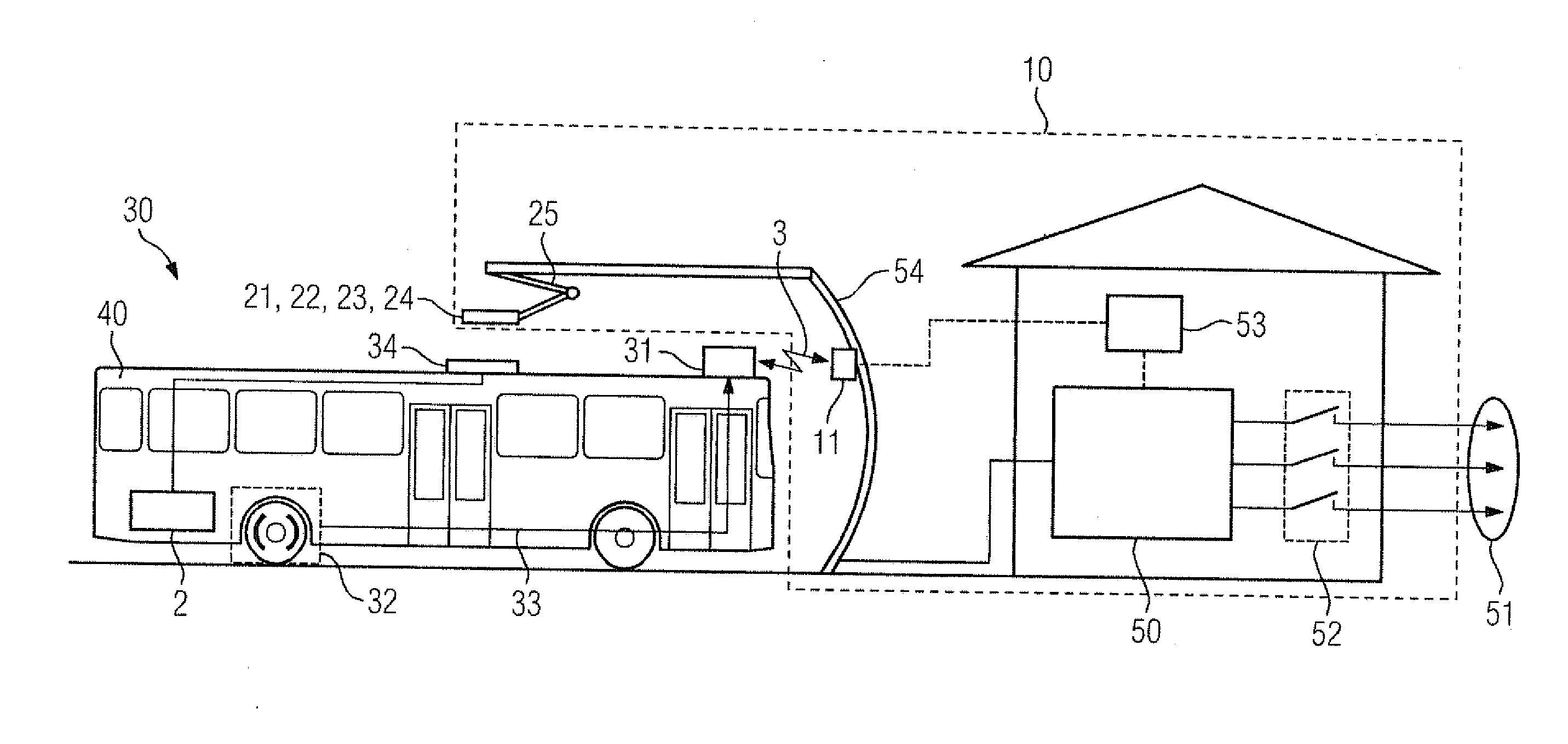
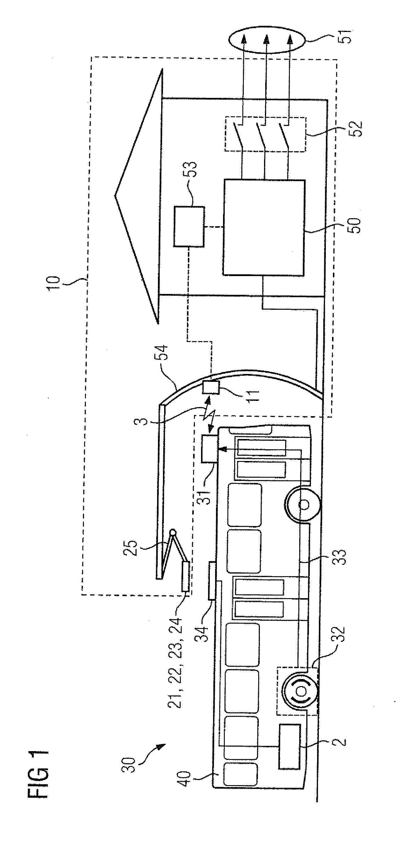
[0034]Turning now to the drawing, and in particular to FIG. 1, there is shown a schematic illustration of a system with a vehicle 30 in the form of a bus with an energy accumulator 2 and a charging station 10. The charging station 10 has a mast 54 to which a current collector 25 is attached. The contacts 21, 22, 23, 24 of the charging station 10 can be placed in contact with...


PUM


Abstract

In a method of charging an energy accumulator of a vehicle in a charging station, the presence of a vehicle is ascertained in a defined region in vicinity of the charging station via a wireless communication between a vehicle-side communication device and a communication device of the charging station. The charging process of the energy accumulator in the charging station is cleared, when the wireless communication between a vehicle-side communication device and a communication device of the charging station is established and a parking brake of the vehicle is activated.

Description

CROSS-REFERENCES TO RELATED APPLICATIONS[0001]This application claims the priority of European Patent Application, Serial No. 14197729.8, filed Dec. 12, 2014, pursuant to 35 U.S.C. 119(a)-(d), the disclosure of which is incorporated herein by reference in its entirety as if fully set forth herein.BACKGROUND OF THE INVENTION[0002]The present invention relates to a charging method for an energy accumulator of a vehicle, and to a charging station, to a vehicle, and to a system that includes a vehicle and a charging station.[0003]The following discussion of related art is provided to assist the reader in understanding the advantages of the invention, and is not to be construed as an admission that this related art is prior art to this invention.[0004]As a result of the need to reduce CO2, those responsible in an increasing number of cities are considering to use in public transportation vehicles, in particular buses, which either have purely electric propulsion or are equipped at least ...

Claims


Application Information

Patent Timeline
Patent Type & Authority Applications(United States)
IPC IPC(8): B60L11/18
CPCB60L11/1824B60L11/182Y02T90/16Y02T90/14Y04S30/14B60L5/42B60L2200/18B60L2200/30B60L2240/30B60L53/14B60L53/30B60L53/36B60L53/65B60L53/665B60L53/305B60L53/62Y02T10/7072Y02T10/70Y02T90/12Y02T90/167
Inventor BOLIK, ULRICHLASKE, ANDREASMULLIGAN, LIAMSCHMITT, ANTON
Owner SIEMENS AG
Why Eureka
Try Eureka