Method for producing a glass ceramic element with patterned coating

a technology of glass ceramics and coatings, applied in the field of glass ceramic articles, can solve the problems of difficult to produce very fine patterns, high set-up costs, and easy smearing

Inactive Publication Date: 2016-06-16
SCHOTT AG
View PDF12 Cites 15 Cited by
  • Summary
  • Abstract
  • Description
  • Claims
  • Application Information

AI Technical Summary

Benefits of technology

[0012]The invention is based on the object to improve the creation of patterned coatings on glass ceramic substrates so as to provide for more flexibility in patterning and to be able to produce finer patterns than is possible with screen printing. In addition, with screen printing only the coating itself is patterned. However, it may be desired to additionally modify the glass ceramic in the portions of the glass ceramic element that remain uncoated.
[0014]For concealing the display elements or other technical items below the glass ceramic in the region of the window or pattern feature, a translucent coating may be used according to one embodiment. Alternatively, a translucent film matched in color may be inserted between light emitting elements and the windows or pattern feature in the glass ceramic. This achieves both, visibility of the display element and a homogeneous aesthetic appearance for the operator looking at the utilization side of the cooktop.

Problems solved by technology

However, it is difficult to produce very fine patterns such as thin lines, for example.
Moreover, when very fine or small logos are to be produced the ink tends to smear, causing rejects.
Furthermore, for every new product request or design change a new screen needs to be created, so that set-up costs are very high, which is especially noticeable in small series.
Manufacturing of individual designs for each end user is therefore expensive.
Furthermore, for multilayer coatings in case of a printing technique such as screen printing the problem arises that congruent patterning is difficult.

Method used


Image

  • Method for producing a glass ceramic element with patterned coating
  • Method for producing a glass ceramic element with patterned coating
  • Method for producing a glass ceramic element with patterned coating

Examples


Embodiment Construction

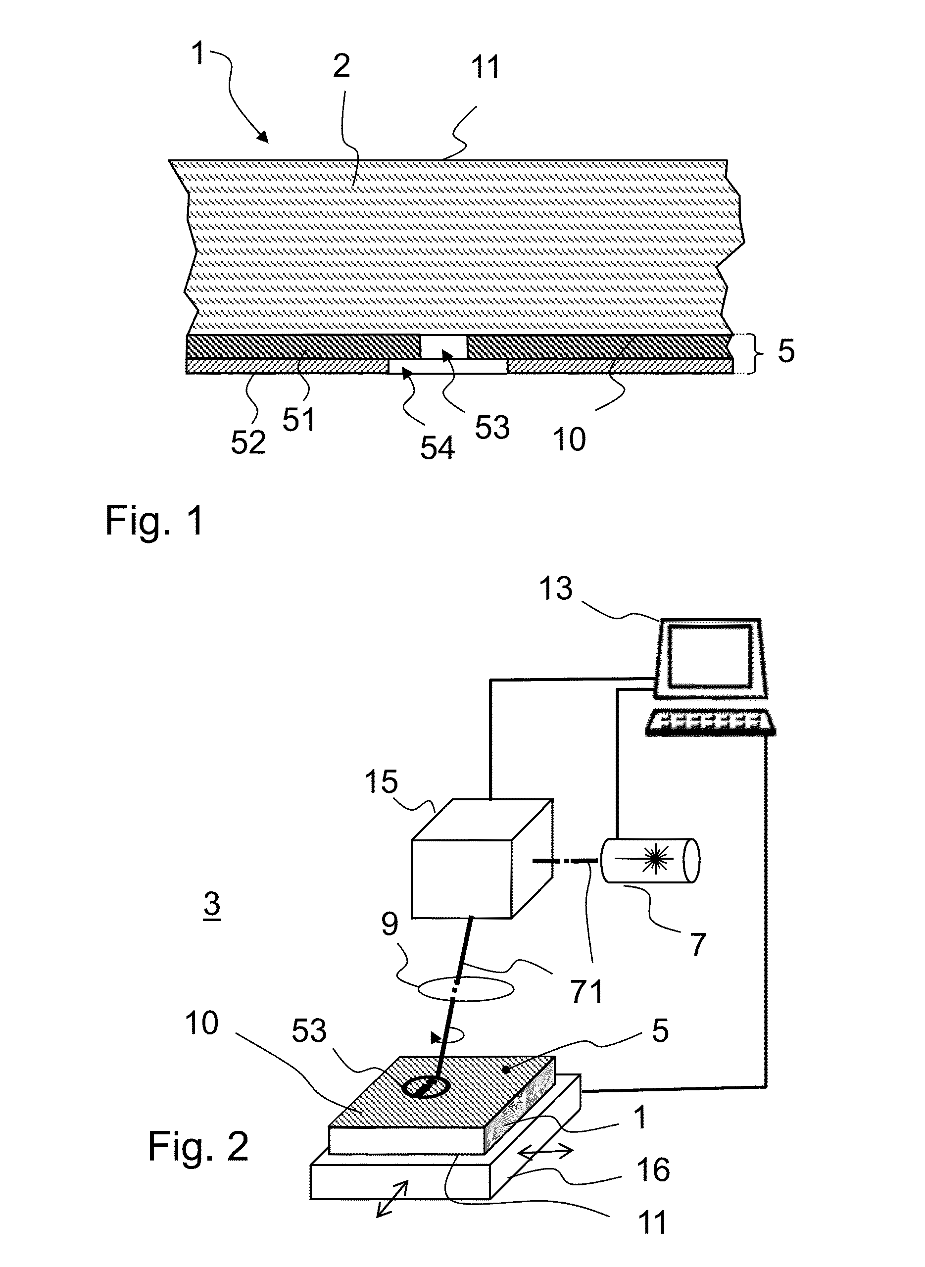
[0025]For a more detailed description of a glass ceramic element 1 that is provided with a patterned coating, reference is first made to the example of FIG. 1 which comprises a coating 5 produced by conventional screen printing. The plate-shaped glass ceramic element 1 has two opposite faces 10, 11. In case of a glass ceramic element in the form of a glass ceramic cooking plate, one of the faces 10, 11 is the utilization side.

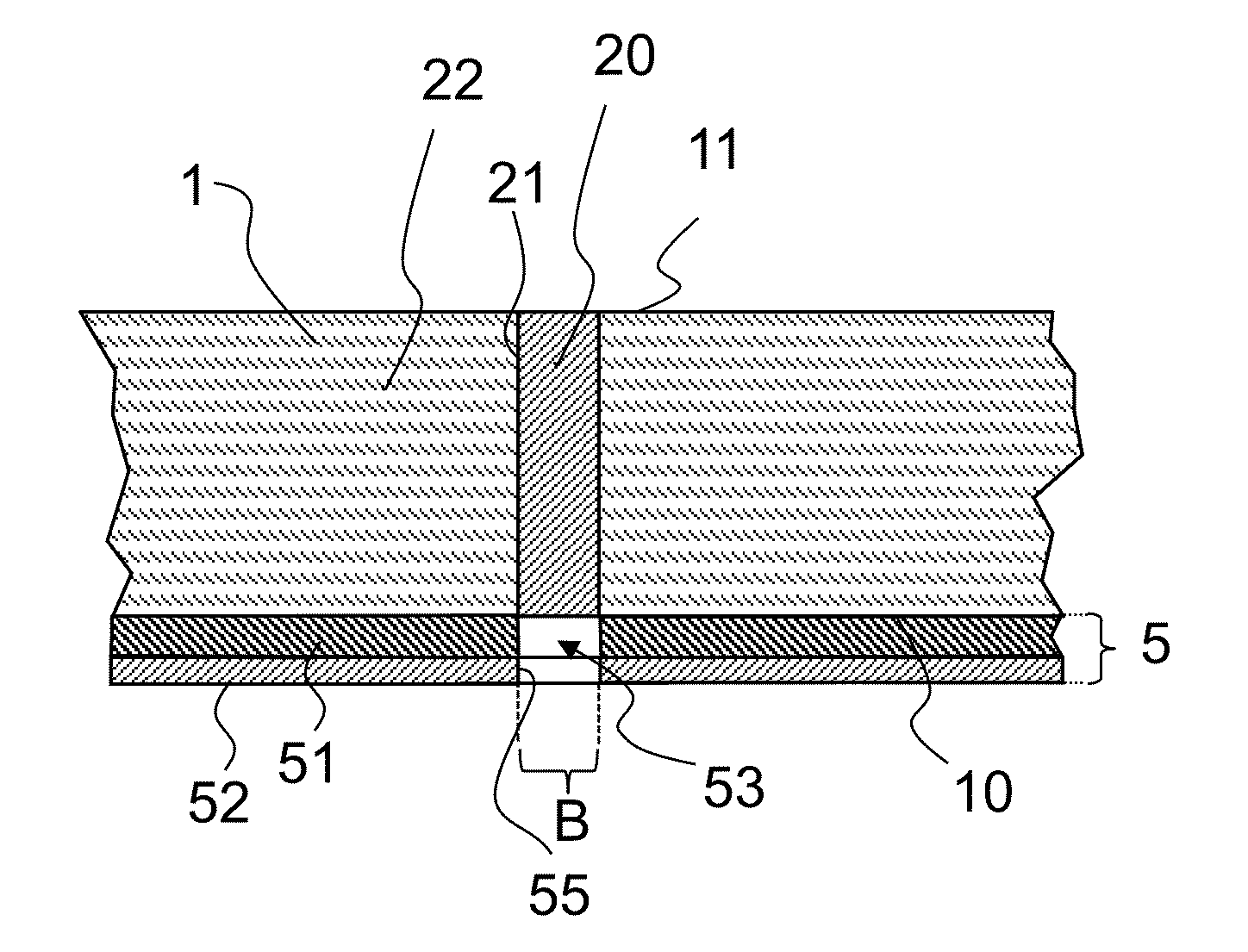
[0026]The coating 5 on at least one of faces 10, 11 is a multilayer coating consisting of a first ink layer 51 on the glass ceramic 2 and a second ink layer 52 applied to the first ink layer 51. First ink layer 51 includes a pattern feature 53. This pattern feature is defined by a region in which the glass ceramic 2 remains free, that means it is not coated there. The contour of this pattern feature may, for example, take the shape of a logo, lettering, or an icon. Due to the patterned discontinuity of the ink layer, light can pass through the glass ceramic ele...


PUM

PropertyMeasurementUnit
wavelengthaaaaaaaaaa
distanceaaaaaaaaaa
distanceaaaaaaaaaa

Abstract

A method is provided for producing a glass ceramic element with a patterned coating is provided. The method includes: providing a glass ceramic element with a coating which is at least partially light-blocking and preferably opaque in the visible spectral range; irradiating the glass ceramic element with a pulsed laser beam on the face provided with the coating so that the coating is removed by ablation; during irradiating the laser beam is directed over the surface of the glass ceramic element so that a portion of the coating is removed which has a greater lateral extent than the diameter of the laser beam; and once the coating has been removed, irradiating the glass ceramic with the laser in the region where the coating has been removed, thereby optically modifying the glass ceramic in the irradiated region.

Description

[0001]This application claims benefit under 35 U.S.C. §119(a) of German Patent Application No. 10 2014 118 497.1 filed Dec. 12, 2014 and German Patent Application No. 10 2015 103 518.9 filed Mar. 10, 2015, the entire contents of both of which are incorporated herein by reference.BACKGROUND OF THE INVENTION[0002]1. Field of the Invention[0003]The invention generally relates to glass ceramic articles that are provided with patterned coatings. More particularly the invention relates to glass ceramic articles which have translucent features in coatings.[0004]2. Background of the Invention[0005]From the prior art, glass ceramic cooktops are known which are coated on the lower surface in order to modify the appearance and to conceal parts of the cooktop installed below the glass ceramic.[0006]One option for this purpose are sol-gel coatings which are quite heat resistant and are distinguished by good adhesion to the glass ceramic plate. For concealing internal parts of a cooktop, opaque c...

Claims


Application Information

Patent Timeline
Patent Type & Authority Applications(United States)
IPC IPC(8): F24C15/10B23K26/362
CPCF24C15/105F24C15/102B23K26/362B32B17/06B41M5/24B41M5/262B23K26/0624B23K26/082B23K26/361B23K2101/34B23K2103/50B23K2103/52C03C23/0025C03C2218/328F24C15/10Y10T428/24331Y10T428/24355Y10T428/2457Y10T428/24802Y10T428/24893Y10T428/24901Y10T428/24926Y10T428/24942B23K26/36B32B3/263B32B3/266B32B3/30B32B5/142B32B5/147B32B18/00B32B2307/41B32B2307/412B32B2307/414B32B2310/0843B32B2509/00B23K26/352B23K26/354B23K26/359B23K26/53B23K26/3584B23K2103/54C03C4/0071C03C17/002C03C17/22C03C17/23C03C17/34C03C2201/30C03C2201/34C03C2201/40C03C2201/42C03C2201/54C03C2217/70C03C2217/72C03C2218/36
Inventor WAGNER, FABIANWALDSCHMIDT, HOLGER
Owner SCHOTT AG
Why Eureka
Try Eureka