Ejector

Active Publication Date: 2016-06-16
DENSO CORP
View PDF1 Cites 6 Cited by
  • Summary
  • Abstract
  • Description
  • Claims
  • Application Information

AI Technical Summary

Benefits of technology

The present patent aims to provide an ejector that can prevent its body size from becoming too large and to maintain the efficiency of the ejector. One way to achieve this is by using a conical shape for the passage formation member, which helps to limit the increase in the size of the ejector. The mixing passage is also designed to accelerate the mixed refrigerants and to prevent droplets (drops of liquid-phase refrigerant) from adhering to the inner and outer surfaces of the ejector. This allows the droplets to be effectively mixed with the gas-phase refrigerant and to transmit their velocity energy to the gas-phase refrigerant. As a result, the kinetic energy of the mixed refrigerants is limited, reducing the pressure increase in the diffuser passage and improving the efficiency of the ejector.

Problems solved by technology

Accordingly, an increase of dimensions in the axial direction of the diffuser passage is limited, and an increase in the volume of the entire ejector can be limited.

Method used


Image

  • Ejector
  • Ejector
  • Ejector

Examples


first embodiment

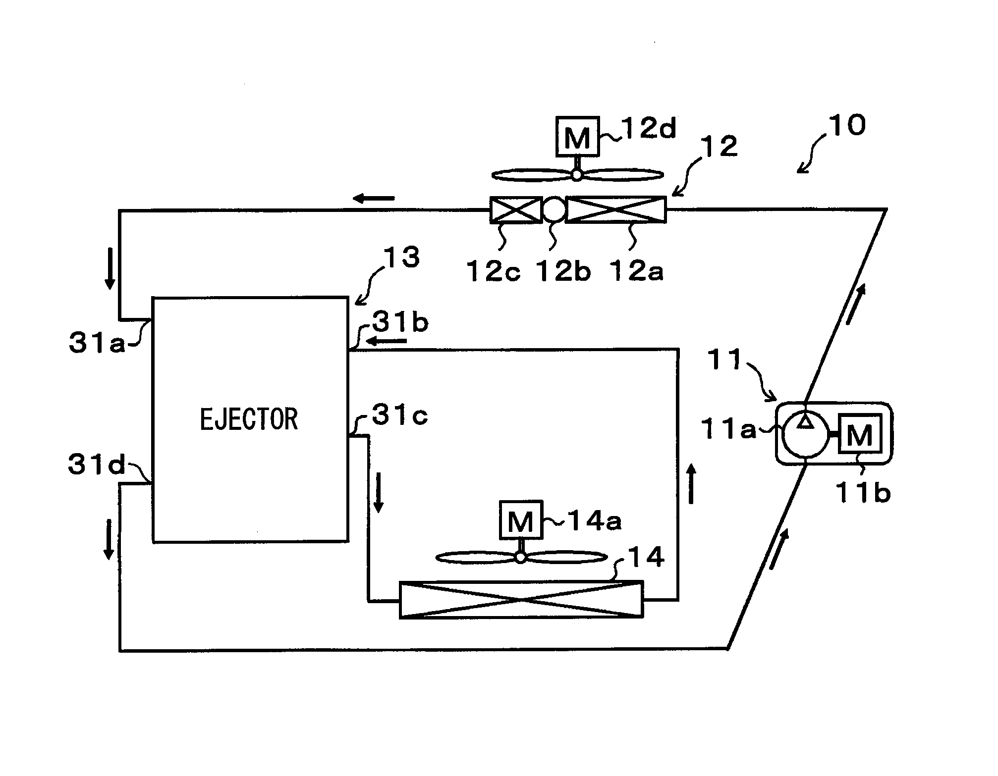
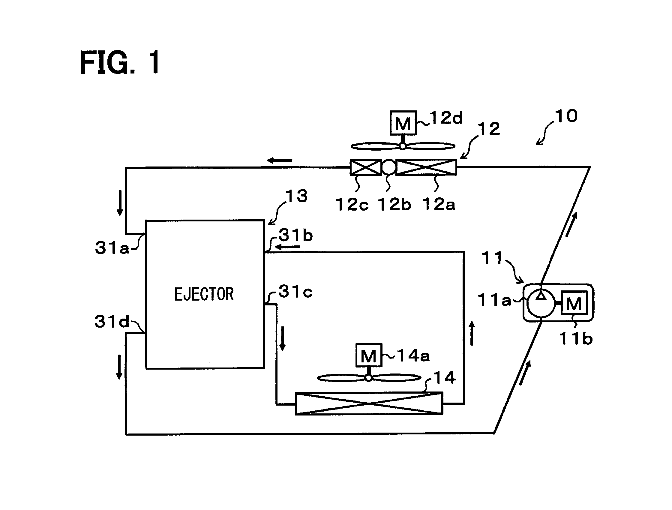
[0059]A first embodiment of the present disclosure will be described with reference to FIGS. 1 to 5. As illustrated in FIG. 1, an ejector 13 of this embodiment is applied to a vapor compression refrigeration cycle device including an ejector as a refrigerant depressurizing device, that is, an ejector refrigeration cycle 10. Moreover, the ejector refrigeration cycle 10 is applied to a vehicle air conditioning apparatus, and performs a function of cooling blast air which is blown into a vehicle interior that is a space to be air-conditioned.

[0060]The ejector refrigeration cycle 10 employs an HFC based refrigerant (specifically, R134a) as the refrigerant, and forms a subcritical refrigeration cycle in which a high pressure-side refrigerant pressure does not exceed a critical pressure of the refrigerant. The ejector refrigeration cycle 10 may employ an HFO based refrigerant (specifically, R1234yf) or the like as the refrigerant. Furthermore, refrigerator oil for lubricating a compressor...

second embodiment

[0158]In an ejector refrigeration cycle 50 of this embodiment, as illustrated in an overall configuration view of FIG. 6, the ejector 13 according to the first embodiment is replaced with an ejector 53, and a branch part 15 that branches the refrigerant flow that has flowed out of an evaporator 14 is added.

[0159]The branch part 15 includes a three-way joint having three inlet / outlet ports. One of the three inlet / outlet ports is set as a refrigerant inlet port, whereas the remaining two inlet / outlet ports are set as refrigerant outlet ports. One refrigerant outlet port of the branch part 15 is connected with a refrigerant suction port 31b of the ejector 53, and the other refrigerant outlet port of the branch part 15 is connected with a second refrigerant suction port 31f provided in a housing body 31 of the ejector 53.

[0160]As illustrated in FIG. 7, the ejector 53 according to this embodiment is added with a second suction passage 13e having the refrigerant outlet configured to be op...

third embodiment

[0195]Since the ejector 53 described in the second embodiment has two refrigerant suction ports of the first refrigerant suction port 31b and the second refrigerant suction port 31f, the ejector 53 can be applied to the ejector refrigeration cycle variously configured. Under the circumstances, in this embodiment, an ejector 53 is applied to an ejector refrigeration cycle 60 illustrated in FIG. 9. In the ejector refrigeration cycle 60, a branch part 15 is disposed in a liquid-phase refrigerant outlet port 31c of the ejector 53.

[0196]Further, one refrigerant outlet port of the branch part 15 is connected with a refrigerant inlet side of a first evaporator 14 (corresponding to the first evaporator 14 in the first embodiment), and a refrigerant outlet side of the first evaporator 14 is connected with a first refrigerant suction port 31b of the ejector 53. The other refrigerant outlet port of the branch part 15 is connected with a refrigerant inlet side of a second evaporator 17, and the...


PUM


Abstract

In an ejector, a passage formation member is disposed inside a body forming a space therein. Provided between an inner peripheral surface of the body and the passage formation member are a nozzle passage functioning as a nozzle, a mixing passage in which an ejection refrigerant ejected from the nozzle passage and a suction refrigerant drawn through a suction passage are mixed together, and a diffuser passage that converts a kinetic energy of the refrigerant that has flowed out of the mixing passage into a pressure energy. The mixing passage has a shape gradually reducing in cross-sectional area toward a downstream side in the refrigerant flow.

Description

CROSS REFERENCE TO RELATED APPLICATION[0001]This application is based on and incorporates herein by reference Japanese Patent Application No. 2013-157580 filed on Jul. 30, 2013.TECHNICAL FIELD[0002]The present disclosure relates to an ejector that depressurizes a fluid, and draws the fluid by a suction action of an ejection fluid ejected at high speed.BACKGROUND ART[0003]Up to now, ejectors have been known as a depressurizing device applied to a vapor compression refrigeration cycle device. The ejector of this type has a nozzle portion that depressurizes refrigerant, draws a gas-phase refrigerant which has flowed out of an evaporator due to a suction action of an ejection refrigerant ejected from the nozzle portion, mixes the ejection refrigerant with the suction refrigerant in a pressure increase part (diffuser portion), thereby being capable of increasing the pressure.[0004]Accordingly, in a refrigeration cycle device (hereinafter, referred to as an ejector refrigeration cycle) in...

Claims


Application Information

Patent Timeline
IPC IPC(8): F25B41/00F04F5/44F25B9/08F04F5/10
CPCF25B41/00F04F5/10F25B2500/18F25B9/08F04F5/44F25B5/02F25B6/02F25B40/02F25B2327/001F25B2341/0012F25B2400/0407F25B2400/23F04F5/463B60H2001/3298F25B41/335
Inventor YOKOYAMA, YOSHIYUKIYAMADA, ETSUHISANISHIJIMA, HARUYUKI
Owner DENSO CORP
Why Eureka
Try Eureka