

Multicomponent magnetic field sensor
a multi-component, magnetic field technology, applied in the direction of magnetic sensor geometrical arrangement, magnetic field offset compensation, magnetic measurement, etc., can solve the problem of large installation space, high manufacturing complexity of 3d sensor, and the requirement of space for detecting a plurality of magnetic field components, etc., to achieve the highest magnetic field sensitivity and maximum sensitivity
- Summary
- Abstract
- Description
- Claims
- Application Information
AI Technical Summary
Benefits of technology
Problems solved by technology
Method used
Image

Examples
Embodiment Construction
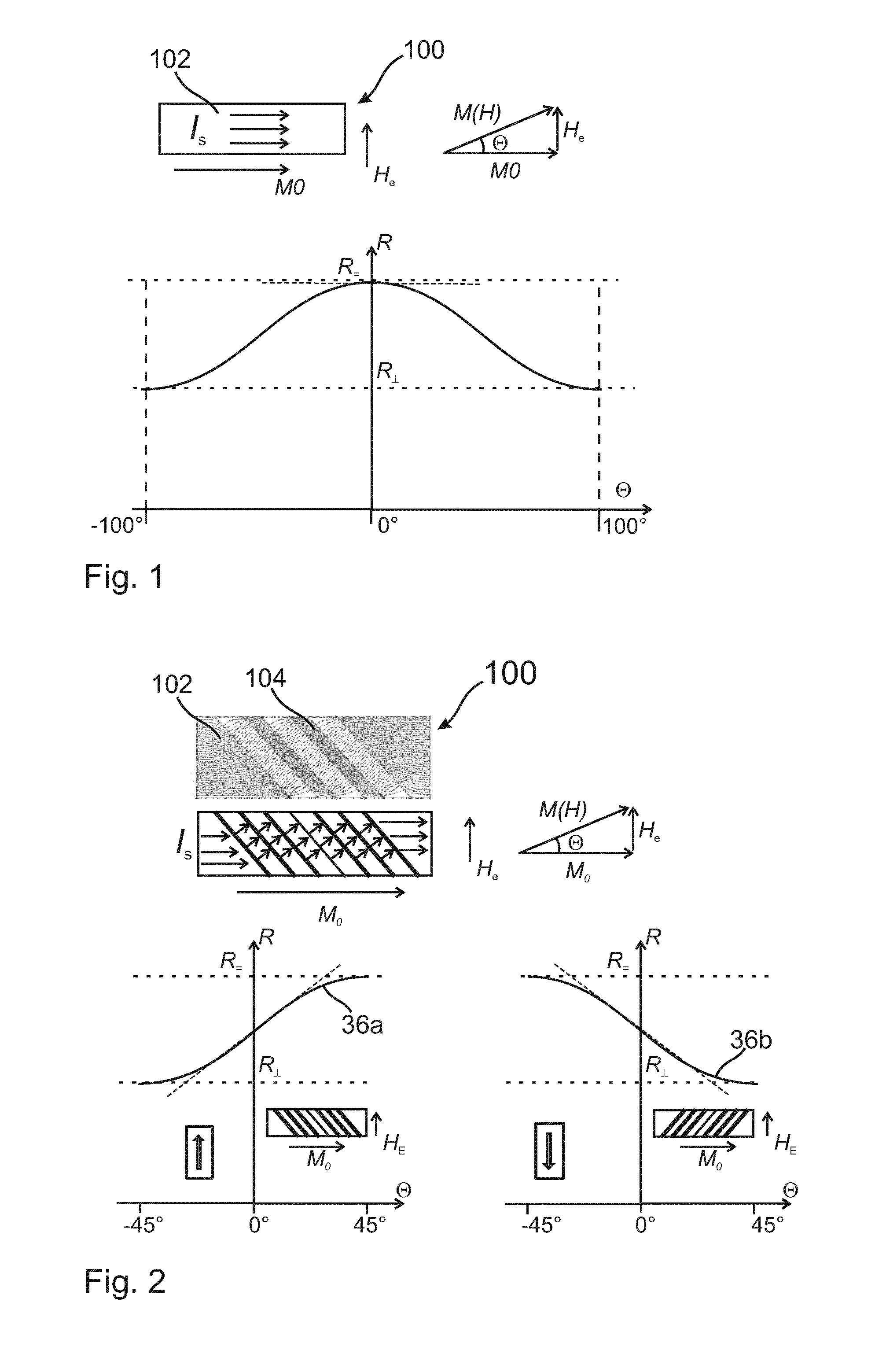
[0037]FIG. 1 shows a resistance characteristic curve as a function of a magnetic field M(H) relative to the direction of a measuring current flux IS through an AMR resistance strip 102 of a magnetic field sensor device 100. The resistance characteristic curve R(M) is determined by the formula R=R⊥+(R∞−R⊥)cos2(Θ), θ representing the angle between the current flow direction ISand an overall magnetic field M(H). The overall magnetic field M(H) is made up of a magnetic field of an internal premagnetisation M0 and an external magnetic field He which is to be measured. It can be seen that in the case of small magnetic fields He0, only a slight change in resistance R occurs when the external magnetic field He changes. Such a configuration is thus disadvantageous, because sensitivity to small magnetic fields is relatively low due to the resistance characteristic curve having only a shallow gradient in this region.
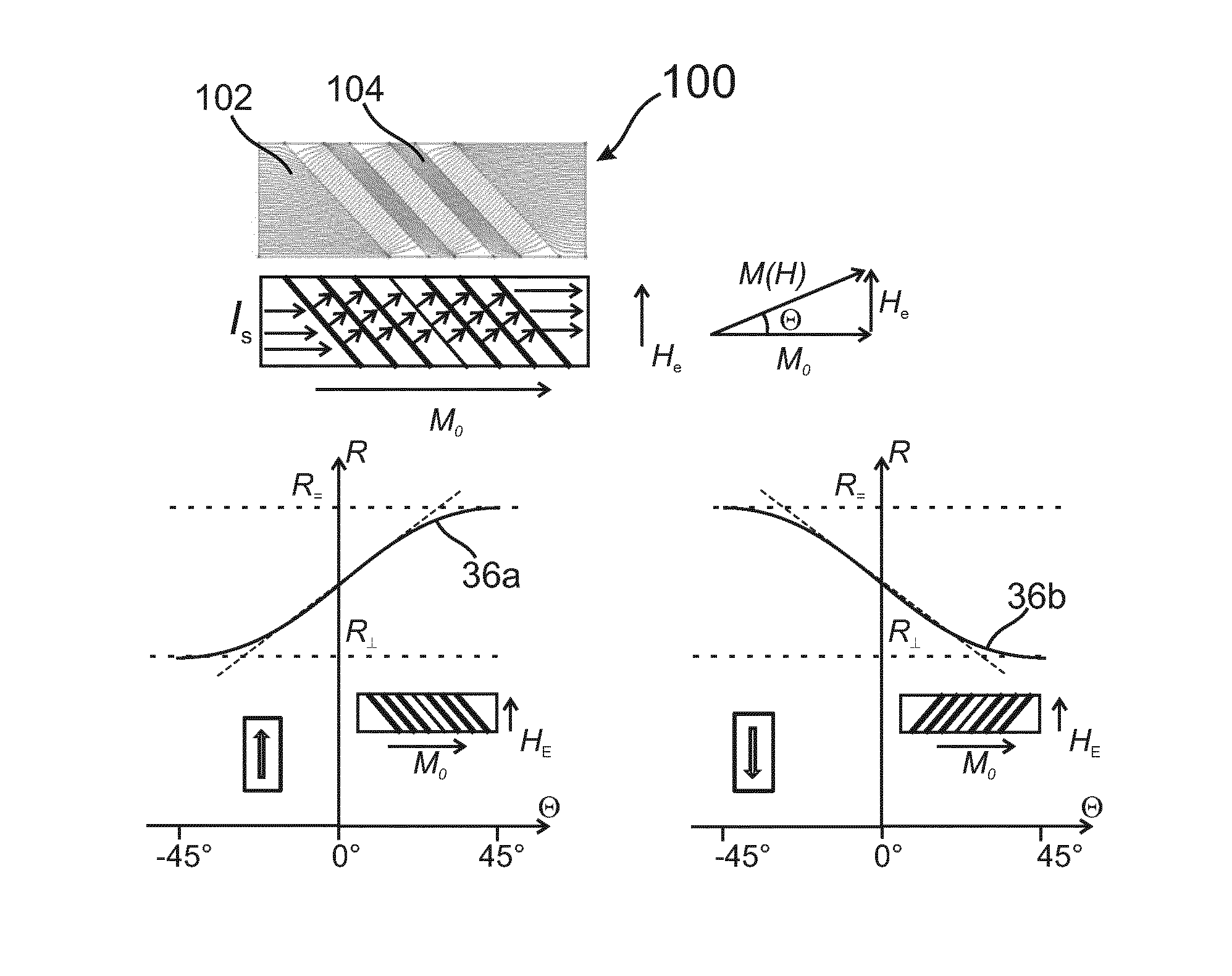
[0038]FIG. 2 shows a prior art AMR resistance device 100 in which an AMR resis...
PUM
 Abstract
Description
Claims
Application Information