

Autonomous mobile device and method for controlling same
- Summary
- Abstract
- Description
- Claims
- Application Information
AI Technical Summary
Benefits of technology
Problems solved by technology
Method used
Image

Examples
embodiment 1
[0027]The following description will discuss an embodiment of the present invention with reference to the drawings.
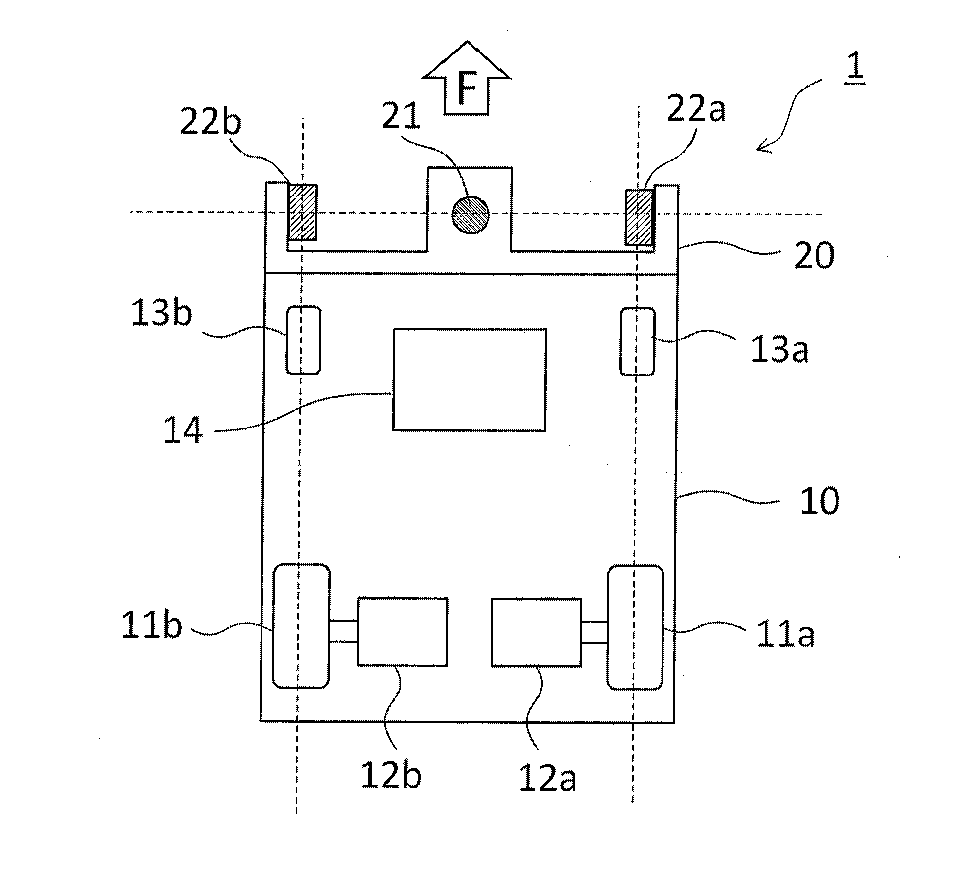
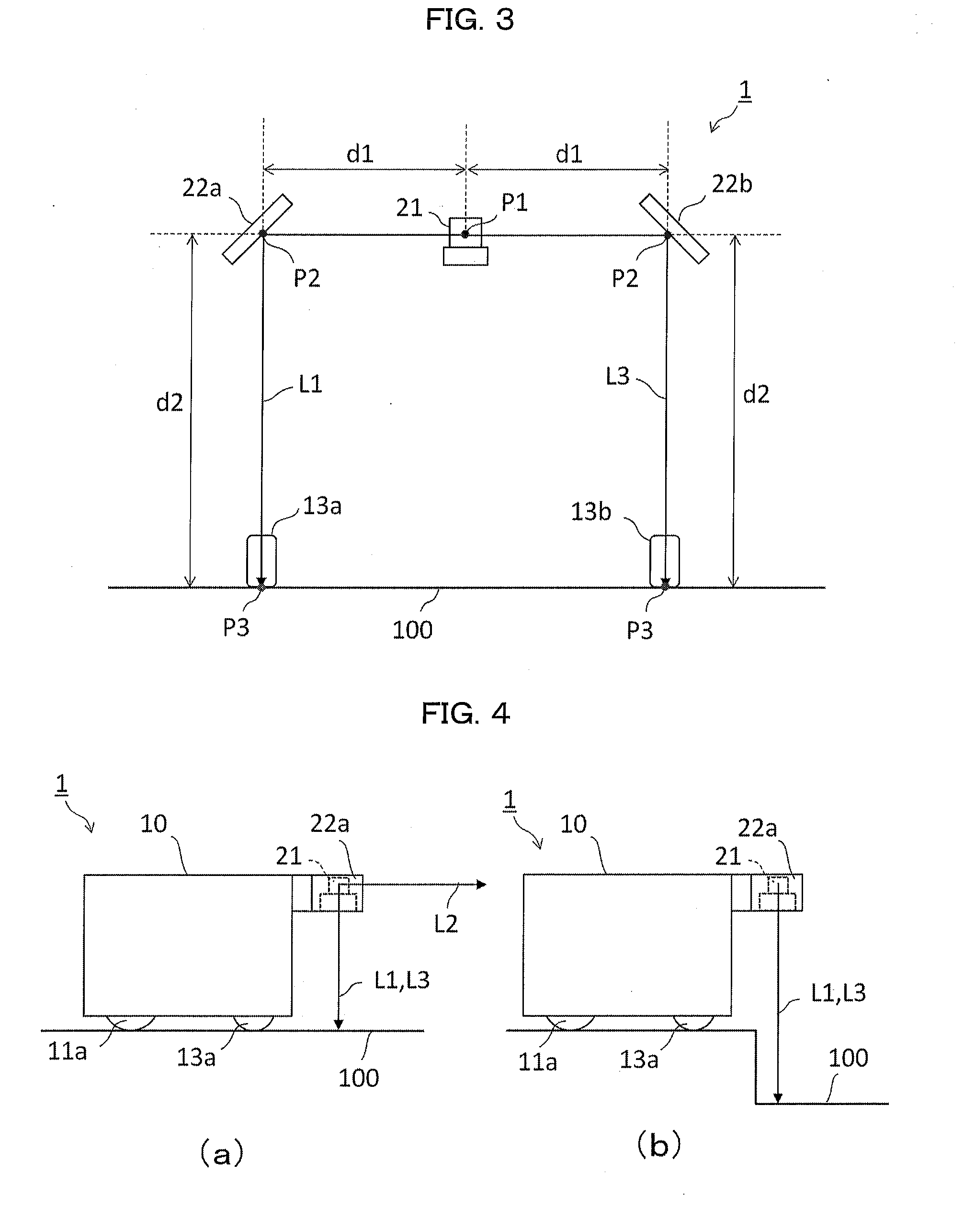
[0028]FIG. 1 is a view schematically illustrating a configuration of an autonomous mobile device 1 in accordance with Embodiment 1 of the present invention. The autonomous mobile device 1 includes a vehicle body 10 and a distance detecting section 20 provided on a front side of the vehicle body 10. The vehicle body 10 has a box shape. The distance detecting section 20 detects an obstacle and a difference in level of a floor surface. A driving wheel 11a, a motor 12a for driving the driving wheel 11a, and an auxiliary wheel 13a are provided on a right side of the vehicle body 10. Similarly, a driving wheel 11b, a motor 12b for driving the driving wheel 11b, and an auxiliary wheel 13b are provided on a left side of the vehicle body 10.
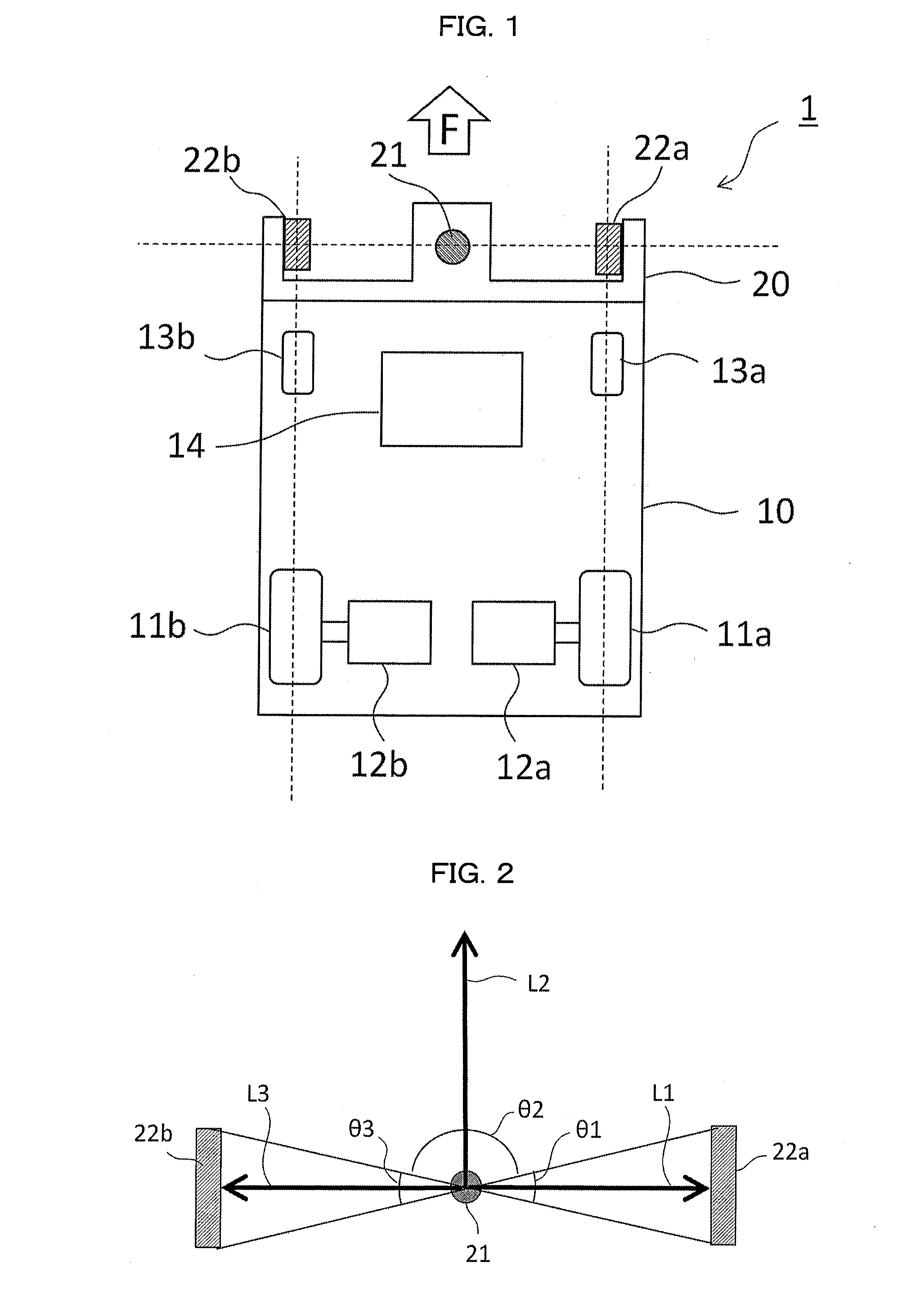
[0029]A laser range finder 21 (LRF), serving as a scanning-type distance sensor, is provided at a middle of the distance detecting section 2...
embodiment 2
[0045]FIGS. 7 and 8 are schematic views for explaining configurations of autonomous mobile devices 2A and 2B, respectively, in accordance with Embodiment 2 of the present invention. The configurations of the autonomous mobile devices 2A and 2B of Embodiment 2 are different from that of the autonomous mobile device 1 of Embodiment 1 in that arrangement of mirrors 22a and 22b is modified. In the other points, the configurations of the autonomous mobile devices 2A and 2B of Embodiment 2 are identical to that of the autonomous mobile device 1 of Embodiment 1 and accordingly, identical descriptions will be omitted.
[0046]According to the configuration of the autonomous mobile device 2A illustrated in FIG. 7, inclination angles of the mirrors 22a and 22b are each set to less than 45 degrees so that positions to which respective laser beams L1 and L3 are emitted are located outside respective moving lines of auxiliary wheels 13a and 13b. The configuration of the autonomous mobile device 2A ...
embodiment 3
[0050]FIG. 9 is a side view for explaining a configuration of an autonomous mobile device 3 in accordance with Embodiment 3 of the present invention. The configuration of the autonomous mobile device 3 of Embodiment 3 is different from that of the autonomous mobile device 1 of Embodiment 1 in that (i) a laser range finder 21 and mirrors 22a and 22b are provided at respective middle positions between a front side and a rear side of a vehicle body 10 and (ii) an auxiliary mirror 28 is further provided. In the other points, the configuration of the autonomous mobile device 3 of Embodiment 3 is identical to that of the autonomous mobile device 1 of Embodiment 1 and accordingly, identical descriptions will be omitted.
[0051]As illustrated in FIG. 9, the autonomous mobile device 3 of Embodiment 3 is configured such that (i) the laser range finder 21 and the mirrors 22a and 22b are provided at the respective middle positions between the front side and the rear side of the vehicle body 10 an...
PUM
 Abstract
Description
Claims
Application Information