Method for indicating proximity, corresponding device, program and recording medium

a technology of proximity and corresponding devices, applied in the field of communication devices, can solve the problems of difficulty for visually impaired users to position their client apparatus close enough, and external help is not recommended

Inactive Publication Date: 2016-06-16
CIE IND & FINANCIERE DINGENIERIE (INGENICO)
View PDF4 Cites 13 Cited by
  • Summary
  • Abstract
  • Description
  • Claims
  • Application Information

AI Technical Summary

Benefits of technology

[0030]Thus, this embodiment makes it possible to vary a characteristic of the sound and / or vibratory signal sent out by the proximity indication module as a function of the very value of the determined indication of proximity.

Problems solved by technology

One major drawback of these techniques lies in the difficulty for a visually impaired user to position his client apparatus close enough to the target apparatus for a communications link to be initiated without being guided by external help.
Indeed, in certain situations of use, external help is not recommended for security reasons, such as for example for contactless electronic payment.

Method used


Image

  • Method for indicating proximity, corresponding device, program and recording medium
  • Method for indicating proximity, corresponding device, program and recording medium
  • Method for indicating proximity, corresponding device, program and recording medium

Examples


second embodiment

6.3. Description of a Second Embodiment

[0102]This second embodiment, which is not shown, provides that the proximity indicating module is integrated into a card case or a card carrier enabling an electronic payment card to be carried in order to implement an NFC type contactless payment as described with reference to the first embodiment.

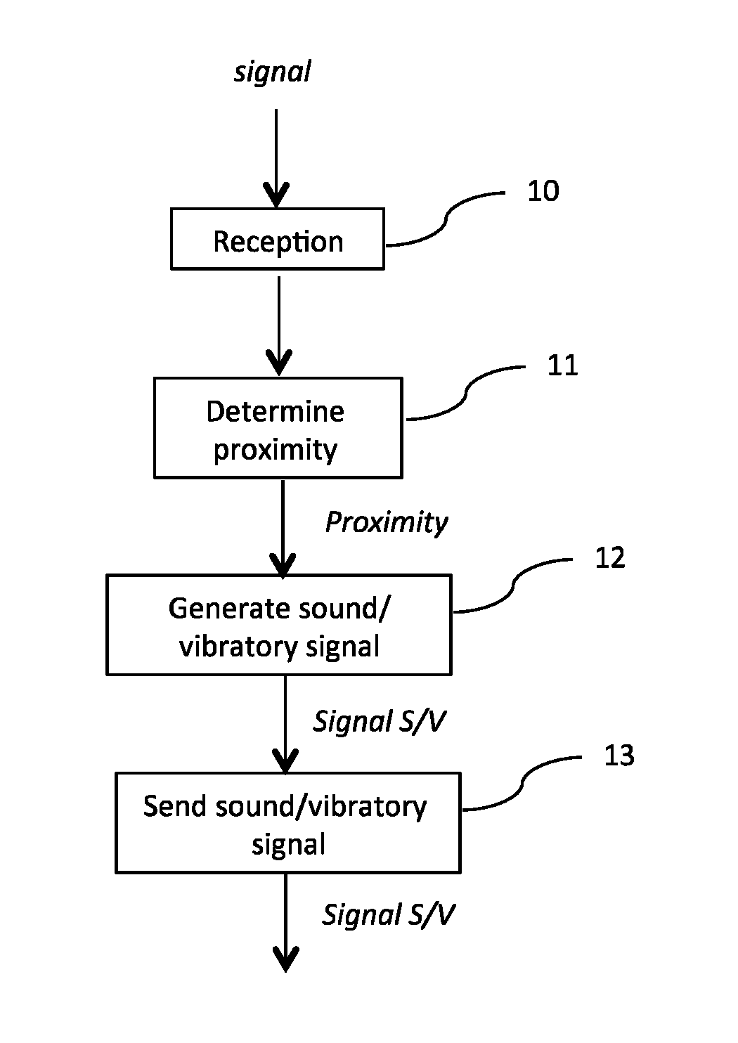
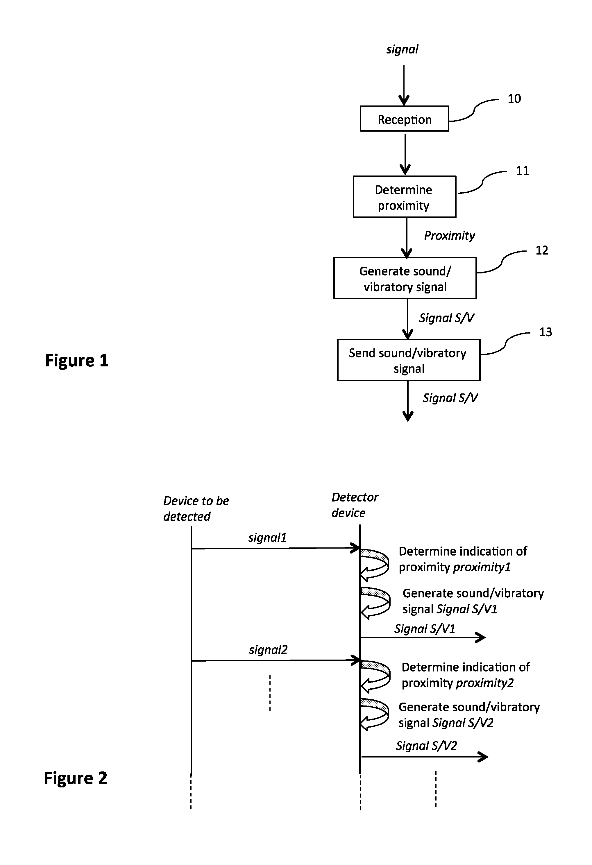
[0103]Thus, according to this second embodiment, it is the bankcard case carrying the user's communications device, namely his contactless payment card, that implements an embodiment of the disclosure, i.e. it detects a signal coming from a device to be detected (in this case an electronic payment terminal), determines a indication of proximity between the case and the electronic payment terminal, and then generates and sends a sound and / or a vibrating signal to inform the bearer of the case as to whether he is approaching or not approaching an electronic payment terminal.

[0104]This second embodiment therefore offers the same advantages as those des...

third embodiment

6.4. Description of a Third Embodiment

[0106]In the first two embodiments described here above, the proximity indicating module is integrated into a client equipment (a mobile terminal or an electronic payment card case) with a view to its interaction with a target apparatus (an electronic payment terminal).

[0107]In this third embodiment, which is not shown, the proximity indicating module is integrated into a target apparatus, for example an electronic payment terminal, with a view to its interaction with a client apparatus.

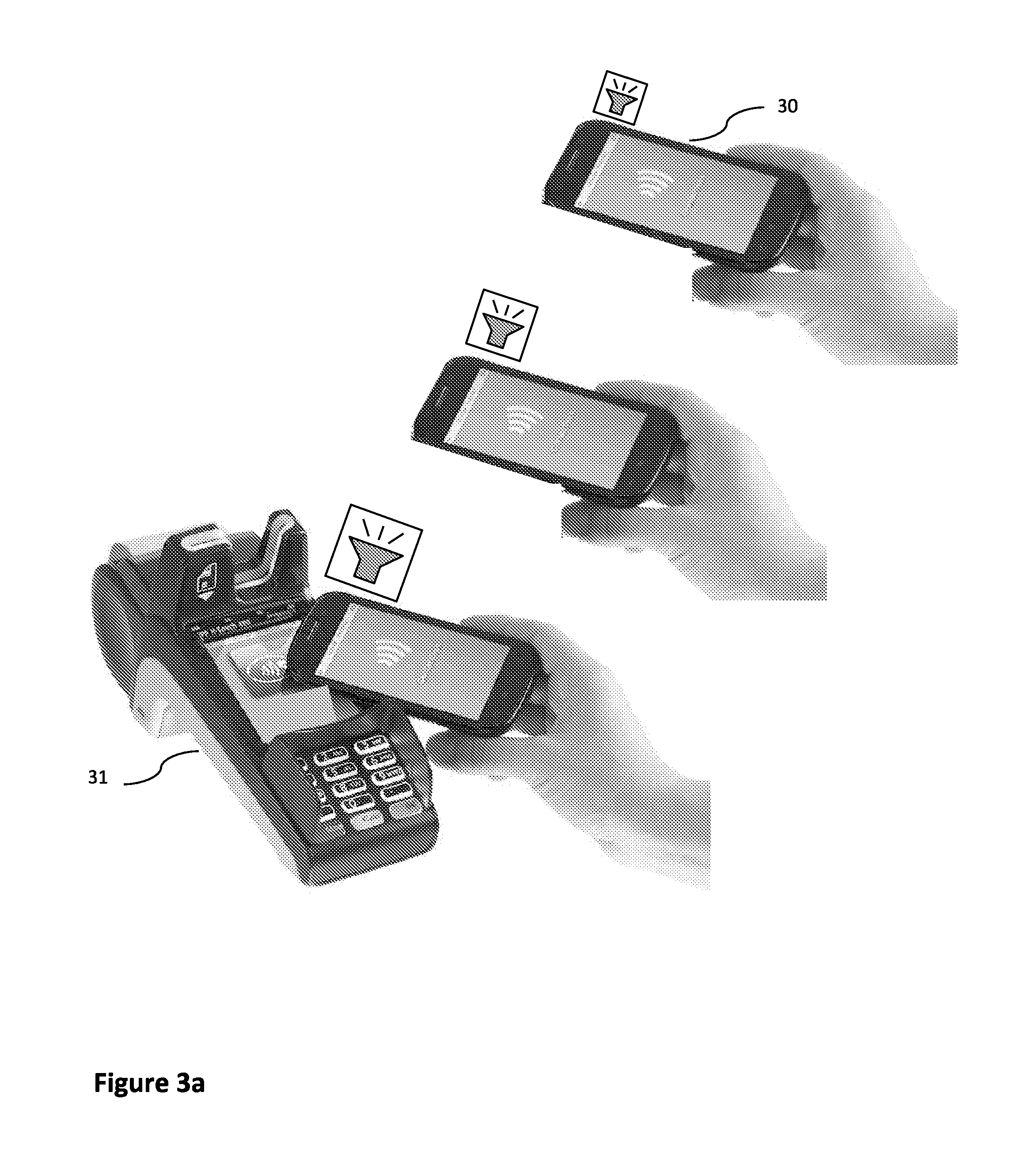
[0108]For example, in the context of an NFC type contactless payment application, it is the electronic payment terminal that implements an embodiment of the disclosure so as to facilitate the approach by a visually impaired user's mobile terminal.

[0109]Thus, it is the electronic payment terminal that detects the signal sent out by the user's mobile terminal (for example a smartphone equipped with Bluetooth Low Energy technology) to determine an indication of prox...


PUM


Abstract

A method and apparatus are provided for indicating proximity between a first communications device, called a detector device corresponding to an electronic card case, and a second communications device called a device to be detected. The method is implemented in a proximity indicating module attached to the detector device. The method includes at least one iteration of the following acts: receiving at least one signal sent out by the device to be detected; determining, from the received signal, at least one indication of proximity between the device to be detected and the detector device; generating at least one sound signal and/or vibration signal representing the determined indication of proximity; and sending the generated sound and/or vibratory signal.

Description

1. CROSS-REFERENCE TO RELATED APPLICATIONS[0001]This Application claims priority to and the benefit of French Patent Application No. FR1462522, filed Dec. 16, 2014, the content of which is incorporated herein by reference in its entirety.2. FIELD OF THE DISCLOSURE[0002]The disclosure pertains to the field of communications devices and more particularly to the detection of proximity or nearness between such communications devices, in order to report this proximity to a user of one of the two devices.3. PRIOR ART[0003]There are known techniques for locating objects, based for example on triangulation calculations using several signals received from several transmitter terminals. These techniques are used for example to exchange data with a device located in a given area, such as for example a user's smartphone when he enters a store.[0004]There also exist known techniques enabling several devices to communicate with one another provided that they are sufficiently close to one another....

Claims


Application Information

Patent Timeline
Patent Type & Authority Applications(United States)
IPC IPC(8): H04W4/02G08B6/00H04W4/00G08B3/10H04M1/72412H04M1/72481H04W4/80
CPCH04W4/023H04W4/008G08B6/00G08B3/10H04W4/80G06Q20/3278G06K19/0712G06K19/0723G06K7/0008G06K7/10297G06Q20/3224G06Q20/327G06Q20/3272G06K19/005G06K19/077G09B21/006G09B21/007G07F7/0886H04M2250/04H04W12/08H04M1/72412H04M1/72481H04L67/75
Inventor MENARDAIS, MICKAELMARSAUD, THIERRY
Owner CIE IND & FINANCIERE DINGENIERIE (INGENICO)
Why Eureka
Try Eureka