
Electro-hydraulic traction support

a technology of electrohydraulic traction and support rod, which is applied in the direction of mechanical equipment, braking systems, transportation and packaging, etc., can solve the problems of weight penalty (affecting vehicle fuel efficiency), wheel can start to spin, and cost penalty for adding components

Active Publication Date: 2016-06-23
CONTINENTAL AUTOMOTIVE SYST INC
View PDF0 Cites 7 Cited by
  • Summary
  • Abstract
  • Description
  • Claims
  • Application Information

AI Technical Summary

Benefits of technology

The present invention is an automotive traction control system that allows for independent control of wheels driven by an engine and torsionally isolated wheels. The system includes sensors, brakes, and motors / hydraulic pumps for each wheel. A clutch is used to connect each secondary axle wheel with its motor / hydraulic pump, and an accumulator is used to power the secondary axle wheels and accept regenerative braking pressure. A wheel valve is also included for selectively connecting each secondary axle wheel's motor / hydraulic pump with the accumulator. The controller manages the primary and secondary axle wheels during low traction events and can command braking and powering of them. Overall, the invention provides greater control and efficiency in maneuvering automotive traction control systems.

Problems solved by technology

When a vehicle has a driven wheel stuck in snow, ice or other low friction surface, the wheel can start to spin.
Wheel spin causes the power from the engine to be delivered to the spinning wheel, while the wheel positioned on a superior traction surface is not powered due to the inherent action of the differential.
The addition of an extra drive shaft, extra differential and transfer case on the vehicle provides a weight penalty (affecting vehicle fuel efficiency) and a cost penalty for added components.

Method used


Image

  • Electro-hydraulic traction support
  • Electro-hydraulic traction support
  • Electro-hydraulic traction support

Examples


Embodiment Construction

[0012]The following description of the preferred embodiment(s) is merely exemplary in nature and is in no way intended to limit the invention, its application, or uses.

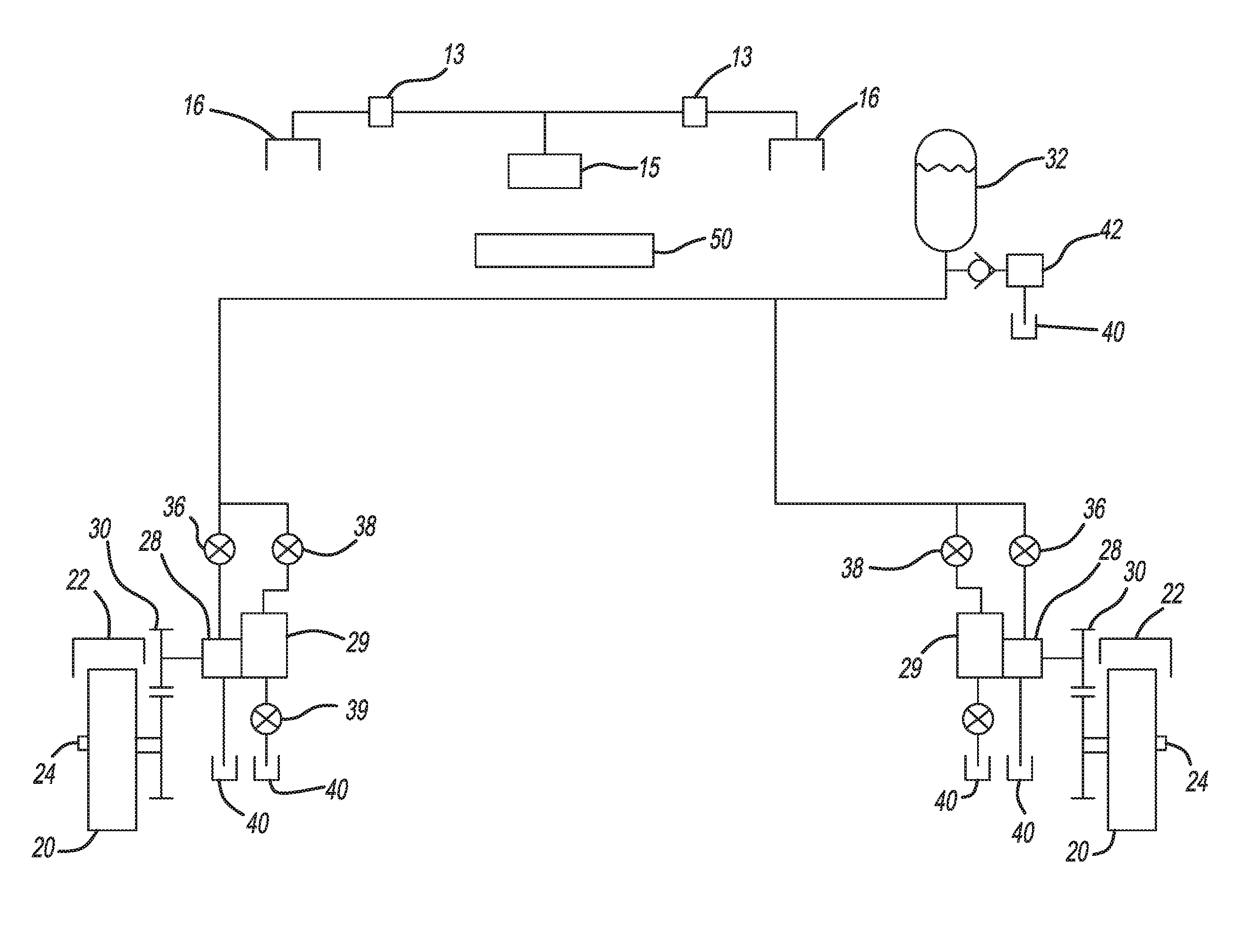
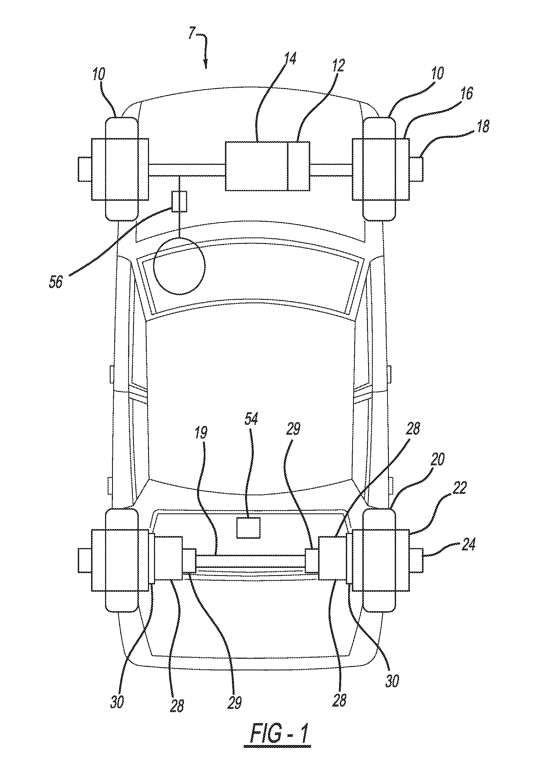
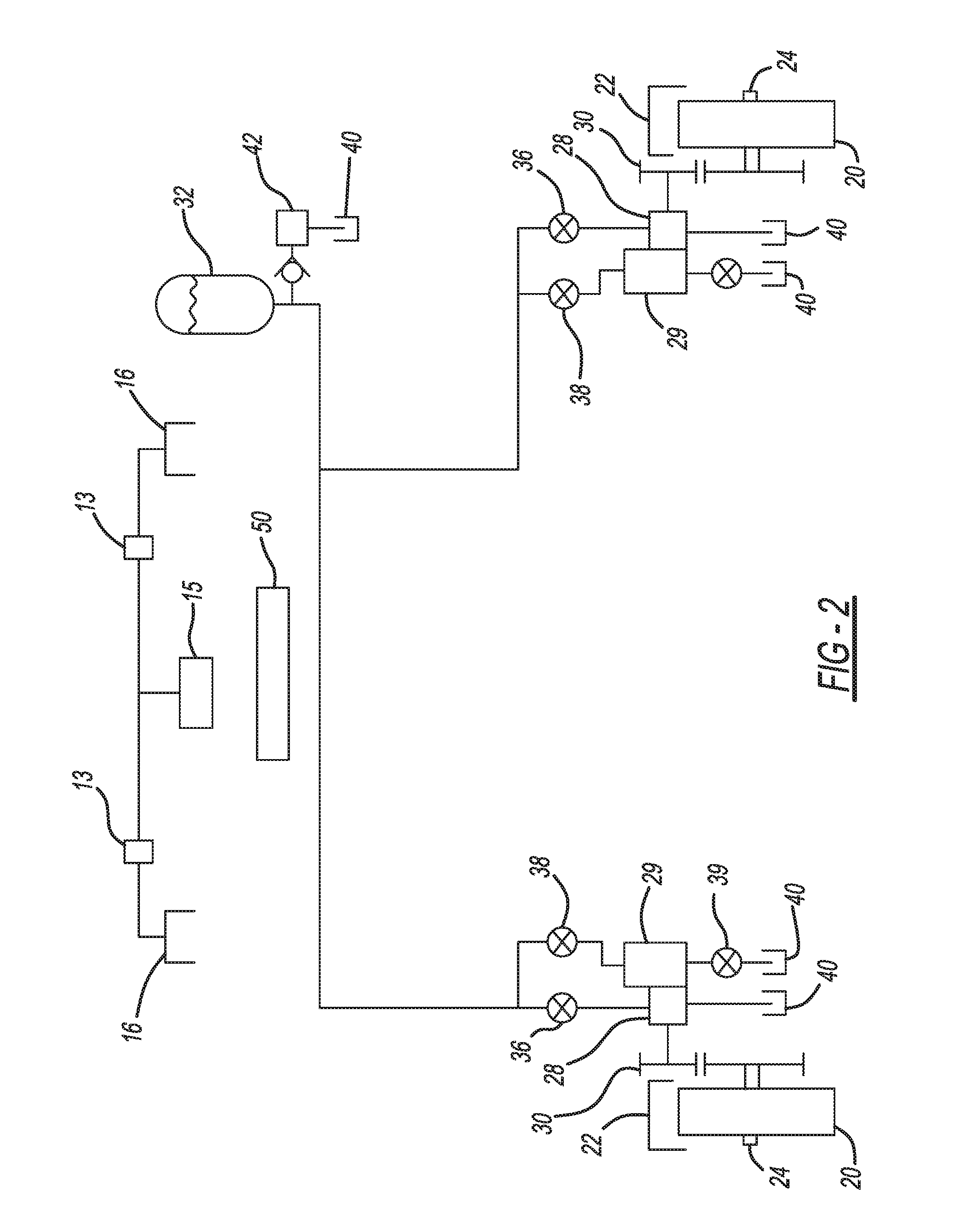
[0013]Referring to FIGS. 1 and 2, a vehicle 7 of the present invention has a traction control system 8 that includes front wheels 10. Powered front wheels 10 are torsionally connected with an engine via a transmission and transaxle 12. Each front wheel 10 has a fluid actuated foundation brake 16 and a sensor 18 to determine potential wheel slip.

[0014]Vehicle 7 also has on a secondary axle 19, two non-driven rear wheels 20 that are torsionally isolated from the engine 14. Each rear wheel has a fluid actuated foundation brake 22 operatively associated therewith and a wheel speed sensor 24 to determine potential wheel slip. Each rear wheel 20 has a motor / hydraulic pump 28 operatively associated therewith for selectively powering the rear wheel 20 or being regenerativly powered by the rear wheel 20. Typically, the hydraul...


PUM


Abstract

A traction control system is provided for a vehicle having wheels driven on a primary axle via an engine, and wheels on a secondary axle torsionally isolated from the engine. Wheel speed sensors and brakes are provided for each wheel. A motor / hydraulic pump is operatively associated with each secondary axle wheel for selectively powering the secondary axle wheel or being regenerativly powered by the secondary axle wheel for regenerative braking. A clutch is provided to connect each secondary axle wheel with the secondary axle wheel's motor / hydraulic pump. An accumulator is provided to hydraulically power the secondary axle wheels and to accept regenerative pressure from the secondary axle wheel's motor / hydraulic pump. A wheel valve is provided for each respective secondary axle wheel for selectively connecting the secondary axle wheel's motor / hydraulic pump with the accumulator. A controller is provided to control the primary axle and secondary axle wheels. The controller commands braking and powering of the primary and secondary axle wheels during low traction events.

Description

PRIORITY[0001]This application is a continuation-in-part of, and claims priority to, U.S. patent application Ser. No. 13 / 707,767, filed Dec. 7, 2012. The Ser. No. 13 / 707,767 application is a non-provisional of, and claims priority to, the Dec. 21, 2011 filing date of U.S. Provisional Patent Ser. No. 61 / 578,573, the entire content of which is incorporated herein by reference.FIELD OF THE INVENTION[0002]The present disclosure relates to automotive vehicles, and particularly to an arrangement and method for providing traction support for vehicles.BACKGROUND OF THE INVENTION[0003]Virtually all automotive vehicles have an engine (or electric motor) that powers two wheels on a common axle via a transmission and differential (for front wheel drive vehicles the differential is often referred to as a transaxle). When a vehicle has a driven wheel stuck in snow, ice or other low friction surface, the wheel can start to spin. Wheel spin causes the power from the engine to be delivered to the sp...

Claims


Application Information

Patent Timeline
Patent Type & Authority Applications(United States)
IPC IPC(8): B60W30/18B60W10/02B60W10/188B60W30/188
CPCB60W30/18172B60W30/188B60W10/02B60W2710/182B60W2400/00B60W2520/28B60W2710/021B60W10/188B60K6/12B60K7/0015B60K17/02B60K17/043B60K17/14B60K2007/0061B60T1/10B60T8/3205B60T10/04B60W2520/14B60W2540/18B60W2720/403B60W2720/406B60T8/4827F16D57/06F16D61/00Y02T10/62
Inventor SCHEIBEL, JOERG
Owner CONTINENTAL AUTOMOTIVE SYST INC
Learn More