Gas turbine fuel pipe comprising a damper

a technology of gas turbine fuel and damper, which is applied in the direction of machines/engines, combustion types, lighting and heating apparatus, etc., can solve the problems of hardware damage and the generation of damping pulsations, and achieve the effect of minimising reducing the requirement of fuel feed pressure, and reducing the build-up of high pulsations

Active Publication Date: 2016-06-23
ANSALDO ENERGIA SWITZERLAND AG
View PDF2 Cites 14 Cited by
  • Summary
  • Abstract
  • Description
  • Claims
  • Application Information

AI Technical Summary

Benefits of technology

[0007]According to a first aspect of the invention, there is provided a gas turbine fuel pipe, comprising a fuel line, the fuel line comprising a fuel line volume, a fuel line outer wall and an opening in the fuel line outer wall, a damper comprising a damper volume and a damper outer wall and attached in fluid communication with the fuel line, wherein the damper covers the opening in the fuel line outer wall, and a perforated lining extending across at least part of the opening in the fuel line outer wall. This enables both acoustic decoupling of the fuel line and combustion chamber and can also damp pulsations generated within the fuel line. Damping can also occur over a range of frequencies.
[0008]In general, a perforated pipe damper (or damper) for the fuel distribution system (FDS) of a gas turbine combustor is a reactive damper with dissipation. The reactive features are due to the expansion chamber (damper volume), while the dissipation is due to the interacti...

Problems solved by technology

Furthermore, this damper can damp pulsations that are generated inside the fuel line (fuel feed instability mechanism).
The damper can the...

Method used


Image

  • Gas turbine fuel pipe comprising a damper
  • Gas turbine fuel pipe comprising a damper
  • Gas turbine fuel pipe comprising a damper

Examples


Embodiment Construction

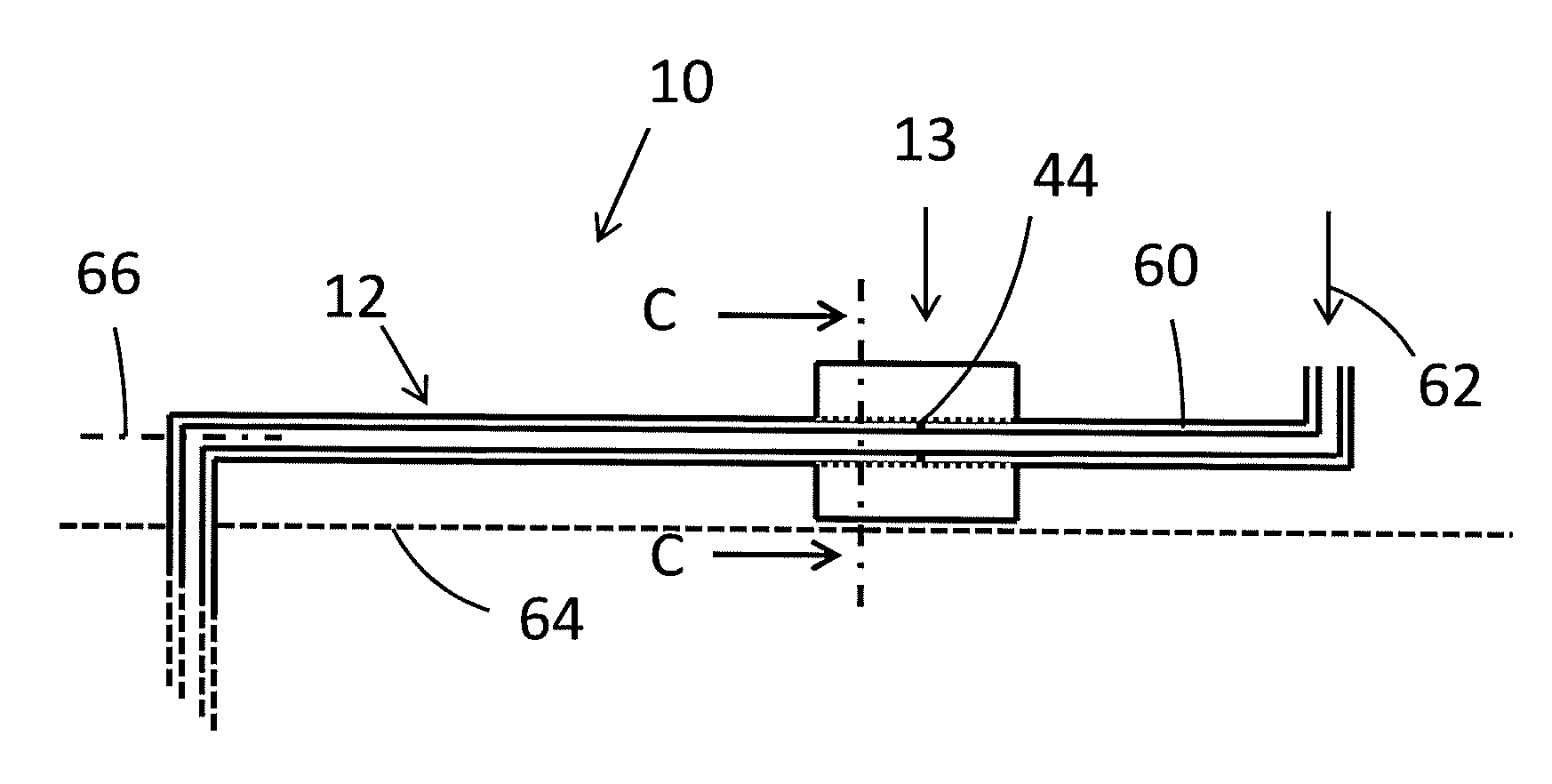
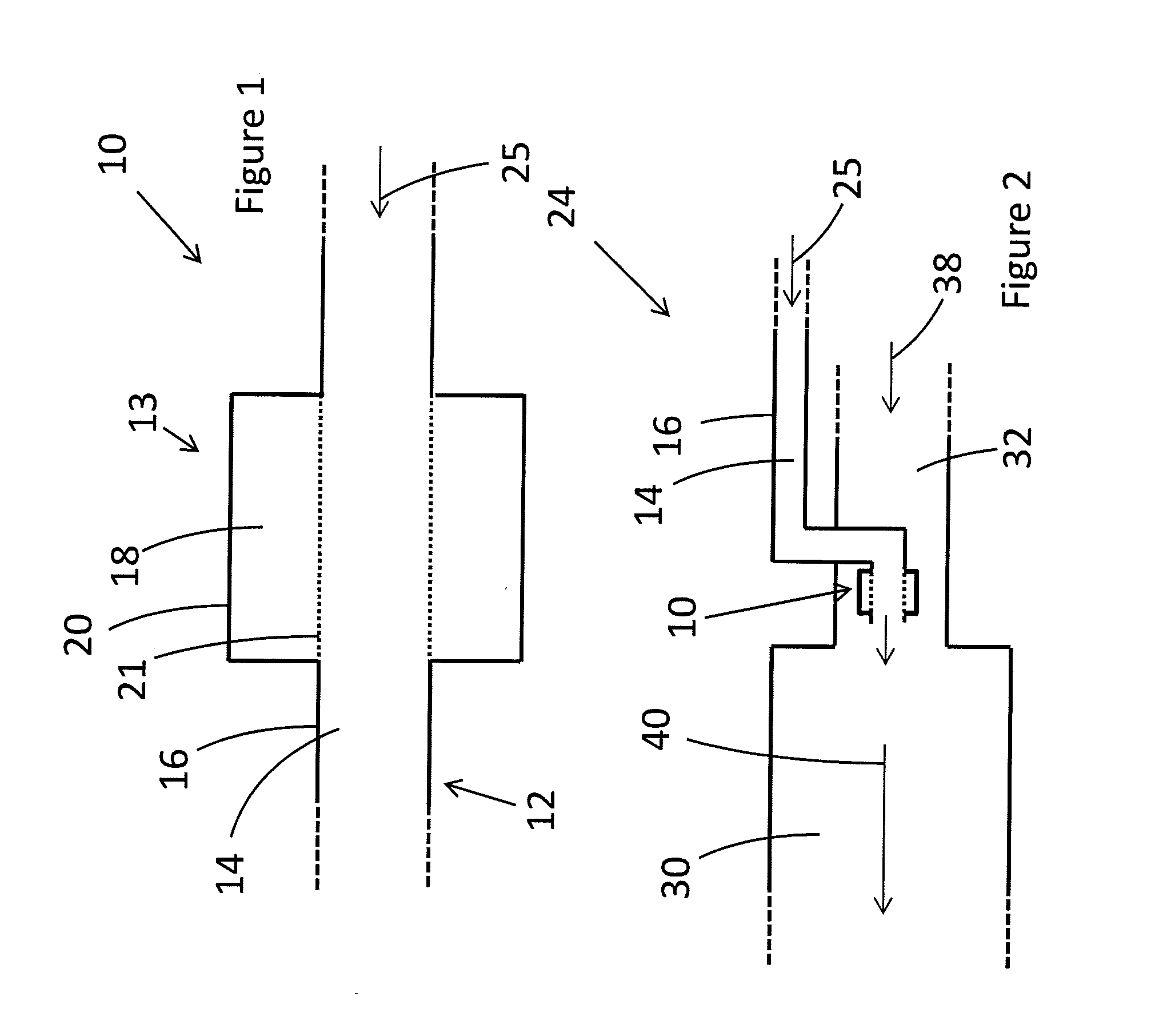
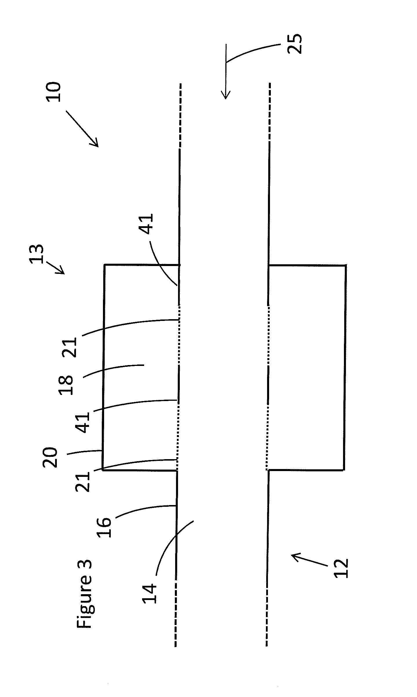
[0033]FIG. 1 shows part of a gas turbine fuel pipe 10 comprising a fuel line 12 and a damper 13. The fuel line 12 comprises a fuel line volume 14, a fuel line outer wall 16 and an opening in the fuel line outer wall. The damper 13 is in fluid communication with the fuel line and is attached to the fuel line to cover the opening in the fuel line outer wall. The damper 13 comprises a damper volume 18 and a damper outer wall 20. A perforated lining 21 extends across the opening in the fuel line outer wall, delineating the edge of the damper volume and the fuel line volume.

[0034]FIG. 2 shows a greater part of the gas turbine fuel pipe shown in FIG. 1 and a partial view of a gas turbine combustor. In addition to features shown in FIG. 1, FIG. 2 also shows a combustion chamber 30 and an air inlet 32. In the embodiment of FIG. 2, a damper is shown downstream of all the 90° angles in the fuel line. One of the 90° angles is in the air inlet, and further upstream, there is a second 90° angle ...


PUM


Abstract

The invention concerns a gas turbine fuel pipe, having a fuel line, the fuel line having a fuel line volume, a fuel line outer wall and an opening in the fuel line outer wall, a damper having a damper volume and a damper outer wall and attached in fluid communication with the fuel line, wherein the damper covers the opening in the fuel line outer wall, and a perforated lining extending across at least part of the opening in the fuel line outer wall. Various embodiments are also described, along with a method of use of the apparatus.

Description

TECHNICAL FIELD[0001]This invention relates to gas turbine fuel pipes, and particularly to gas turbine fuel pipes comprising a damper.BACKGROUND OF THE INVENTION[0002]Acoustic pulsations generate in the combustion chamber of gas turbines due to combustion instabilities. These pulsations can propagate in the fuel distribution system (FDS) and can be a source of equivalence ratio and hence heat release fluctuations that in turn enforce combustion instabilities in the combustor. Another source of pulsations in the FDS is flow-induced pulsations in the fuel line. This fuel feed instability mechanism can give rise to combustion instabilities in the combustion chamber. Pulsations in the FDS have been observed during combustor tests to reach high amplitudes. These high amplitude pulsations generate structural vibrations of the FDS that can be detrimental for structural integrity. Combustion instabilities are detrimental for the performances of combustion systems. They decrease the life-tim...

Claims


Application Information

Patent Timeline
IPC IPC(8): F02C7/22
CPCF02C7/222F05D2260/96F05D2220/32F23R3/28F23R2900/00014F23D2210/00F23D14/46F02C7/22F23D11/36F23M20/005
Inventor WICKSTROM, ANDERS MARTIN AXELTONON, DEVISBOTHIEN, MIRKO RUBEN
Owner ANSALDO ENERGIA SWITZERLAND AG
Why Eureka
Try Eureka