Optical resonance scanner

a scanning device and optical resonance technology, applied in the field of optical scanning devices, can solve problems such as loss of driver efficiency, and achieve the effect of increasing the efficiency of preventing wobbling motion of the magnetizable section

Active Publication Date: 2016-06-23
FEMOTECH
View PDF0 Cites 15 Cited by
  • Summary
  • Abstract
  • Description
  • Claims
  • Application Information

AI Technical Summary

Benefits of technology

[0062]In this manner, it is possible to ensure that forces are always applied vertically into the magnetizable section or the anchor, and that wobbling motions of the same are avoided ...

Problems solved by technology

It has been recognized according to this embodiment of the invention that the scanning devices known from U.S. Pat. No. 5,557,444 A or DE 695 29 530 T2 result in very long magnetic flux paths due to the special arrangement of the electromagnetic driver parts, more particularly due ...

Method used


Image

  • Optical resonance scanner
  • Optical resonance scanner
  • Optical resonance scanner

Examples


Embodiment Construction

[0076]With a view to better readability, structural components of different embodiments that are identical or have the same effect are identified by the same reference signs in the following figures.

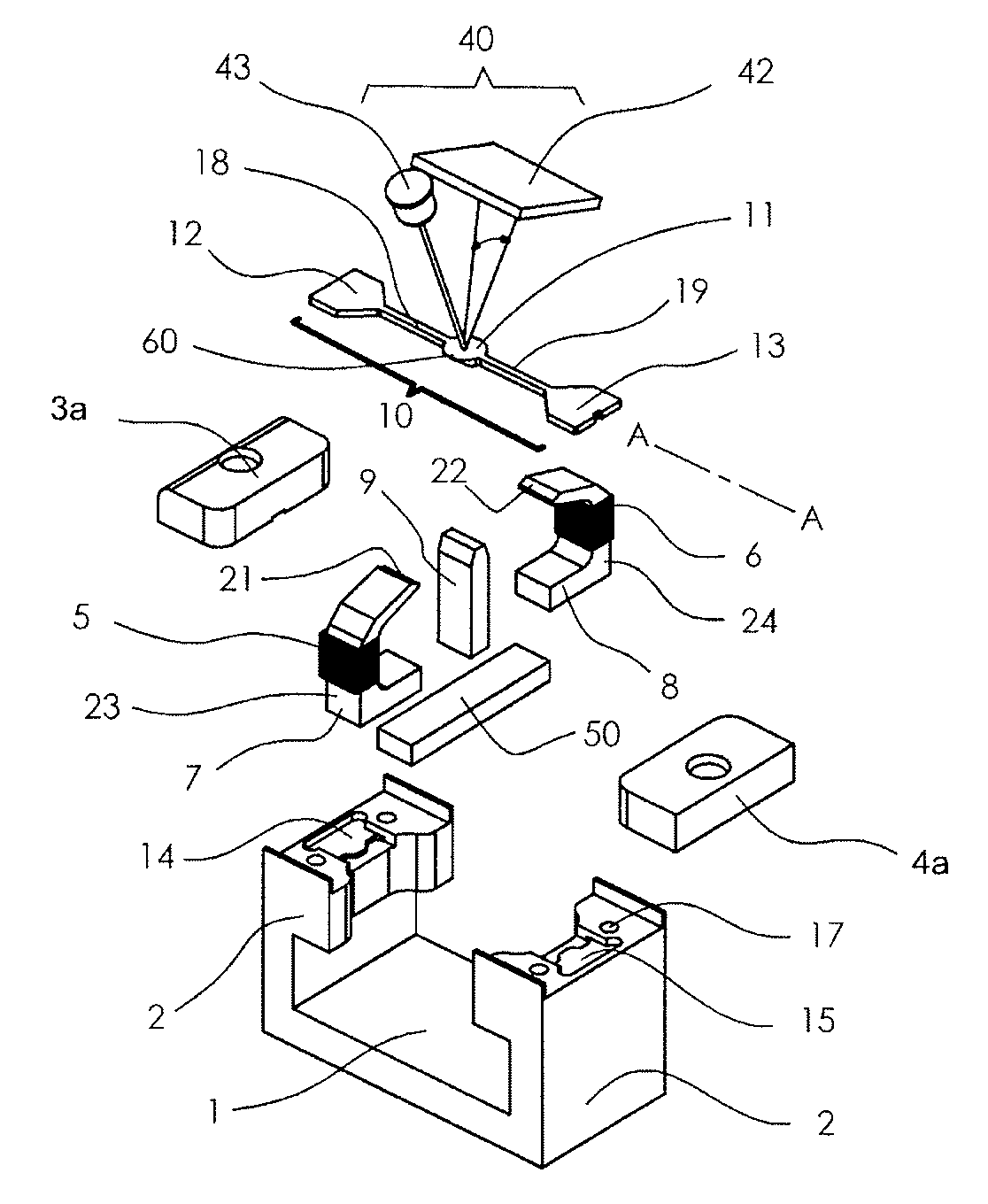
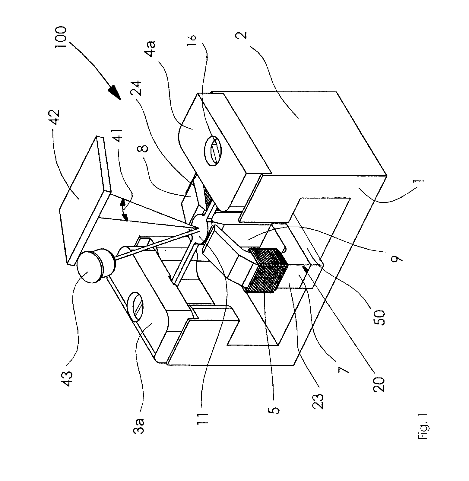
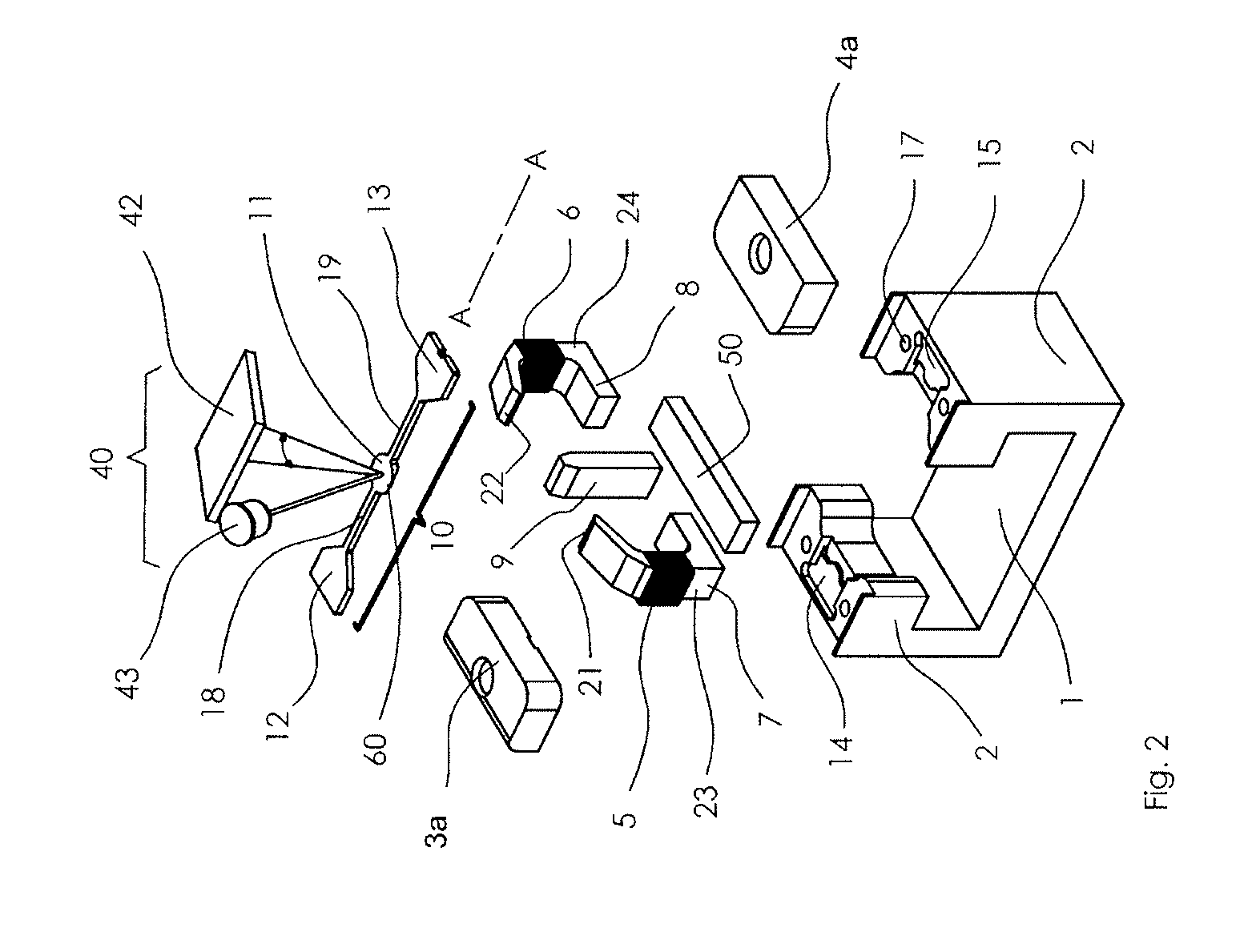
[0077]FIGS. 1-4 show a possible exemplary embodiment of an optical resonance scanner 100, comprising an optical sensor system 40 according to the present invention. The optical sensor system 40 is of the type of a torsional resonance oscillator.

[0078]As far as FIGS. 1 and 2 are concerned, the scanner 100 comprises a substantially C-shaped base plate 1, which forms the mechanical support for the scanner 100. Together with two fixation plates 3a, 4a, the two short flanks of the C-shaped base plate 1 form end brackets 2 for receiving and fixating an elongated, spring-elastic bending element 10. For fixating the bending element 10 or for mounting the fixation plates 3a, 4a on the short flanks of the C-shaped base plate 1, the fixation plates 3a, 4a have recessed screw holes, through which th...


PUM


Abstract

An optical resonance scanner has a spring-elastic bending element (10) excitable to effect rotational oscillations about a longitudinal axis (A-A) using a stationary magnet (9) and a stationary drive coil (5) that is wound around a pole shoe (20). The pole shoe (20) is magnetically coupled to the magnet (9) and has two mutually opposite free ends (21, 22) between which the bending element (10) is arranged symmetrically so that a magnetic flux can be transferred substantially perpendicularly to the longitudinal axis (A-A). In superimposition of the magnet- and coil-induced magnetic fluxes the magnet (9) and a first half (23) of the pole shoe (20) form a first magnetic circuit (30), and the magnet (9) and a second half (24) of the pole shoe (20) form a second magnetic circuit (31), which run in opposite senses with respect to one another in a plane perpendicularly to the longitudinal axis (A-A) through a magnetizable section (6) of the bending element (10).

Description

CROSS-REFERENCE TO RELATED APPLICATIONS[0001]This application is a national stage application (under 35 USC §371) of PCT / EP20141067059, filed Aug. 8, 2014, which claims benefit of German application No. 20 2013 103 566.1, filed Aug. 8, 2013, the contents of each of which are incorporated by reference herein.BACKGROUND OF THE INVENTIONTechnical Field and State of the Art[0002]The invention relates to an optical scanning device, more particularly to an optical resonance scanner, more particularly a torsional resonance oscillator, comprising a spring-elastic bending element, which can be excited to effect oscillations, more particularly to effect rotational oscillations, more particularly sinusoid rotational oscillations, about a longitudinal axis by means of at least one stationary magnet and by means of at least one stationary drive coil, more particularly up to a defined tilt angle, wherein the drive coil is wound around a pole shoe, which is magnetically coupled to a magnet and has...

Claims


Application Information

Patent Timeline
IPC IPC(8): G02B26/10
CPCG02B26/10G02B26/085G02B26/105
Inventor ROSE, ANDREASHERR, GUENTERWEIL, MICHAEL
Owner FEMOTECH
Why Eureka
Try Eureka