Antenna having a reflector for improved efficiency, gain, and directivity

a technology of directivity and reflector, applied in the direction of antennas, electrically short antennas, electrical apparatus, etc., can solve the problems of reducing the radiation efficiency, peak gain, directivity, pifa radiation efficiency, and gain of antenna radiation efficiency and gain by half or more, and achieve the effect of increasing radiation efficiency

Inactive Publication Date: 2016-06-23
SANGARAN PRAGASH +1
View PDF0 Cites 195 Cited by
  • Summary
  • Abstract
  • Description
  • Claims
  • Application Information

AI Technical Summary

Benefits of technology

[0009]The present invention overcomes these and other deficiencies of the prior art by providing an antenna with increased radiation efficiency. One embodiment of the present invention comprises an antenna that is designed to operate in at least one band of frequency, wherein the antenna is formed on a substrate. A reflector is included for each band of frequency the antenna is designed to operate in and is positioned relative to the antenna to redirect electromagnetic radiation of the antenna away from being affected or absorbed by surrounding materials or objects.

Problems solved by technology

Unfortunately, today's users of wireless communication devices want smaller handheld and portable devices.
One limitation in using PIFAs, however, is the ground clearance needed underneath the antenna.
Therefore, any component or printed circuit board (PCB) that lies in parallel to a PIFA will act as a ground extension reducing PIFA radiation efficiency, peak gain, and directivity by half or more.
In today's wireless communication devices, losses in antenna radiation efficiency and gain are inevitable due to electronic components and materials that surround the antenna of the wireless communication device.
These components and materials absorb some of the radiating energy converting it to heat energy and ultimately lowering the efficiency and gain of the devices antenna.

Method used


Image

  • Antenna having a reflector for improved efficiency, gain, and directivity
  • Antenna having a reflector for improved efficiency, gain, and directivity
  • Antenna having a reflector for improved efficiency, gain, and directivity

Examples


Embodiment Construction

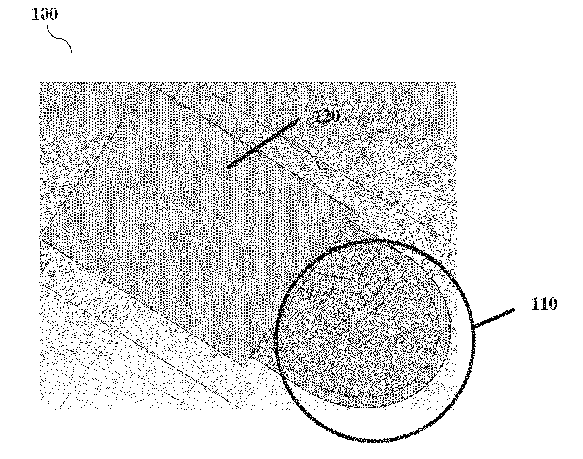
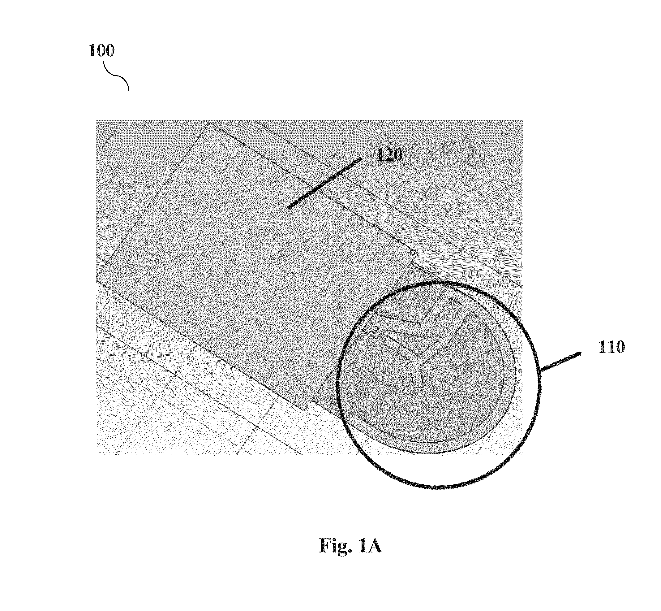
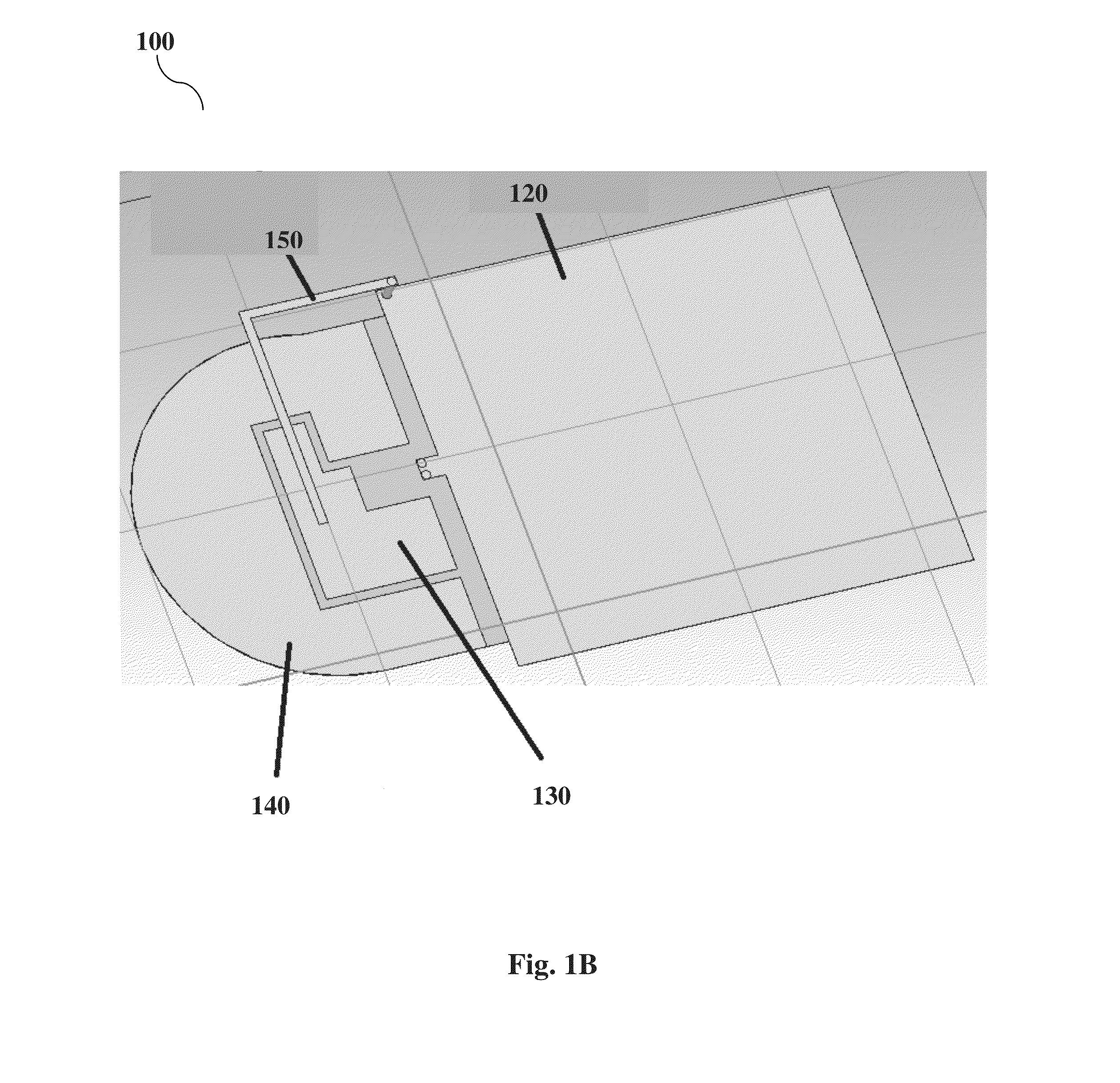
[0019]Preferred embodiments of the present invention and their advantages may be understood by referring to FIGS. 1-3, wherein like reference numerals refer to like elements. Although the present invention is described and illustrated in the context of a PIFA, it is to be understood that the disclosure of the present invention is not limited to a PIFA but is equally applicable to antennas in general, including by way of non-limiting examples, monopole antenna, dipole antenna, folded dipole antenna, loop antenna, slot antenna, cavity-backed slot antenna, inverted-F antenna, slotted waveguide antenna, helical antenna, spiral antenna, short dipole antenna, half-wave dipole antenna, broadband dipole antenna, rectangular patch antenna, patch antenna, folded inverted-F antenna, and any of the PCB or smaller size antennas. In some embodiments, the antenna may be designed on other materials other than PCB such as ceramics, single conductor without substrate and the like. The antenna may be ...


PUM


Abstract

An antenna having at least one reflector for improving radiation efficiency, gain, and directivity is disclosed. The antenna may be formed on a substrate or be a standalone conductive material that is designed to operate in at least one band of frequency. The antenna includes a reflector for each band of frequency the antenna is designed to operate in. The reflector is positioned relative to the antenna to redirect electromagnetic radiation of the antenna away from surrounding materials or objects that affect, i.e., reflect, refract, diffract, absorb and scatter the antenna's electromagnetic radiation.

Description

CROSS-REFERENCE TO RELATED APPLICATION[0001]The present application claims priority to U.S. Provisional Patent Application No. 62 / 052,810, filed on Sep. 19, 2014, entitled “Antenna Miniaturization Technique with Reflector” the entire disclosure of which is incorporated by reference herein.BACKGROUND OF THE INVENTION[0002]1. Field of Invention[0003]This invention relates generally to antenna designs for communication devices and more specifically, to an improved antenna design for communication devices with increased radiation efficiency.[0004]2. Description of Related Art[0005]Wireless communication devices, such as smartphones, laptop computers, tablet computers, access points, health monitoring devices, etc. all make use of multiple antenna types to establish wireless connections between one or more devices. With the advancements being made in wireless technologies, the demand on antennas used in these wireless devices has increasingly called for greater area and volume requiremen...

Claims


Application Information

Patent Timeline
Patent Type & Authority Applications(United States)
IPC IPC(8): H01Q15/14H01Q9/04
CPCH01Q9/04H01Q15/14H01Q9/0421H01Q19/108H01Q5/371
Inventor SANGARAN, PRAGASHMARGON, KEN
Owner SANGARAN PRAGASH
Why Eureka
Try Eureka