Audio switch circuit with slow turn-on

a technology of audio switch and slow turn-on, which is applied in the direction of electronic switching, transducer details, pulse technique, etc., can solve the problems of unfavorable audible noise, such as pops and clicks, and achieve the effect of generating unfavorable audible nois

Active Publication Date: 2016-06-23
SEMICON COMPONENTS IND LLC
View PDF7 Cites 3 Cited by
  • Summary
  • Abstract
  • Description
  • Claims
  • Application Information

AI Technical Summary

Problems solved by technology

One problem with switching audio signals is that undesirable audible noise, such

Method used


Image

  • Audio switch circuit with slow turn-on
  • Audio switch circuit with slow turn-on
  • Audio switch circuit with slow turn-on

Examples


Embodiment Construction

[0015]In the present disclosure, numerous specific details are provided, such as examples of electrical circuits, components, and methods, to provide a thorough understanding of embodiments of the invention. Persons of ordinary skill in the art will recognize, however, that the invention can be practiced without one or more of the specific details. In other instances, well-known details are not shown or described to avoid obscuring aspects of the invention.

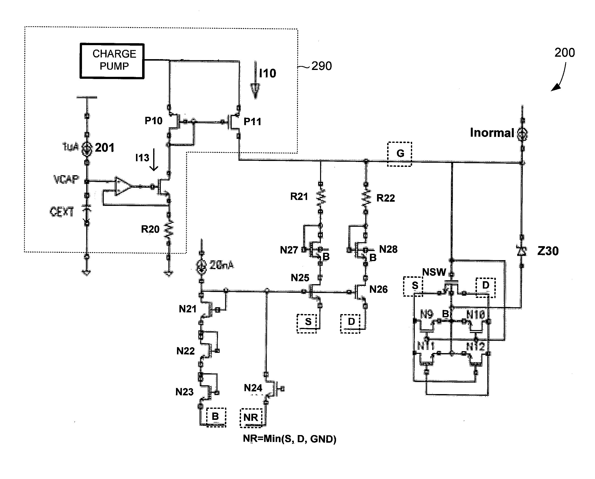
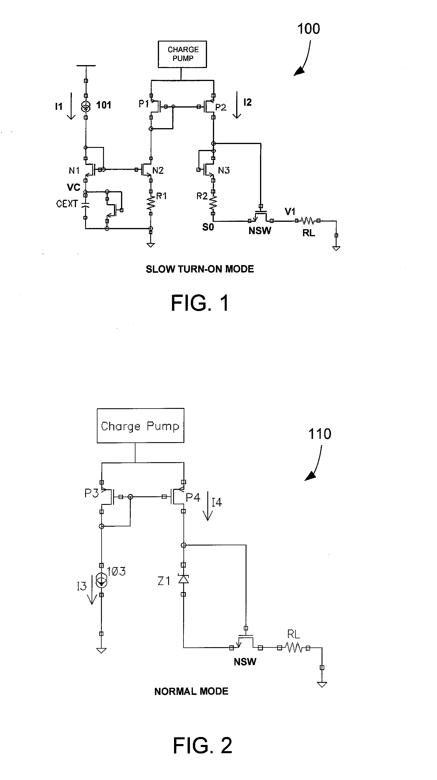
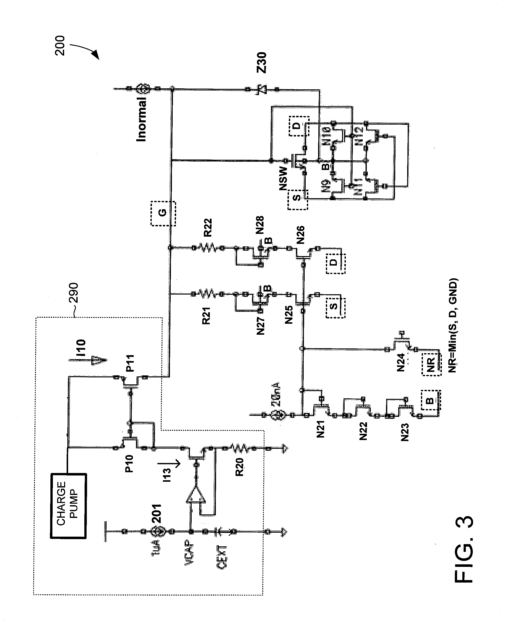
[0016]In the present disclosure, transistors that are labeled with an “N” (e.g., NSW, N1, N2, etc.) are N-type metal oxide semiconductor (NMOS) transistors and transistors that are labeled with a “P” (e.g., P1, P2, etc.) are P-type metal oxide semiconductor (PMOS) transistors. As can be appreciated, the provided transistor types are for illustration purposes only. Other transistors may also be used depending on the particulars of the audio switch circuit.

[0017]FIG. 1 shows a schematic diagram of an audio switch circuit 100 in acco...


PUM


Abstract

An audio switch circuit includes negative feedback paths and a transistor that serves as a switching component. The negative feedback paths are turned ON to couple a source voltage and a drain voltage of the transistor to the gate of the transistor when the audio switch circuit is turned ON. The negative feedback paths reduce the slew rate of the gate-to-source voltage of the transistor, thereby slowing the turn-ON of the audio switch circuit to prevent or minimize unwanted audible noise. The negative feedback paths can be turned OFF after a period of time after the audio switch circuit is turned ON for improved total harmonic distortion.

Description

CROSS-REFERENCE TO RELATED APPLICATION[0001]This application claims the benefit of U.S. Provisional Application No. 62 / 093,040, filed on Dec. 17, 2014, which is incorporated herein by reference in its entirety.BACKGROUND OF THE INVENTION[0002]1. Field of the Invention[0003]The present invention relates generally to electrical circuits, and more particularly but not exclusively to audio switch circuits.[0004]2. Description of the Background Art[0005]An audio switch circuit switches an audio signal from one node to another. Audio switch circuits are employed in a variety of devices, such as in micro Universal Serial Bus switch (MUS) devices. For example, in an MUS device, an audio switch circuit can be employed to switch an audio signal between an audio source and a Universal Serial Bus (USB) port. One problem with switching audio signals is that undesirable audible noise, such as pops and clicks, can be generated when the audio switch circuit is turned ON.SUMMARY[0006]In one embodime...

Claims


Application Information

Patent Timeline
IPC IPC(8): H03K17/687H04R3/00
CPCH04R3/007H03K17/687
Inventor HUANG, LEISTULZ, JULIELI, ERIC
Owner SEMICON COMPONENTS IND LLC
Why Eureka
Try Eureka