
Method for manufacturing panels having translucent elements

a technology of translucent inserts and manufacturing methods, which is applied in the direction of decorative arts, building components, applications, etc., can solve the problems of reducing the production efficiency of cementitious mortar, wasting expensive materials (optical fibers), and limiting the production of rejects, so as to reduce production costs, improve the accuracy of positioning translucent inserts, and limit production. the effect of rejects

Inactive Publication Date: 2016-06-30
ITALCEMENTI
View PDF1 Cites 3 Cited by
  • Summary
  • Abstract
  • Description
  • Claims
  • Application Information

AI Technical Summary

Benefits of technology

This patent is about a new method for making cement-based panels with translucent elements. The method has several benefits: it reduces production costs, allows for panels of different thickness without needing to modify the equipment, improves the accuracy of positioning the translucent inserts, increases the end quality of the panel, and allows for the use of alternative materials to PMMA. The method is also reliable and easy to implement at competitive costs.

Problems solved by technology

Only after such operations the above-described transparency effect can be achieved, which is however conditioned by the intensity of the incident light on the block and by the angle of incidence of the same, beyond a given value from which the transparency effect determined by the transport of light by the optical fibers gradually decays, this being an evident limit of such a technique.
Another drawback of the above-described solution is found in the complex positioning of the optical fibers, which requires to prepare a particular fabric as a support to be inserted in subsequent layers into the formworks, alternating with layers of cementitious mortar; furthermore, additional steps of cutting and polishing are required in order to obtain plates or panels from the blocks, which steps imply waste of costly material (optical fibers), especially when parts of considerable size are needed, such as square plates longer than one meter per side.
However, it has been observed that the panels with elements made of PMMA have some drawbacks which require a solution in order to make this technology easily usable.
It has been additionally observed that the production process of the panels includes a substantially crafted, and in particular a manual, arrangement of the chains in the formworks according to a predetermined arrangement which requires particular care and diligence by workers, the simultaneous use of multiple formworks and the cementitious mortar pouring operations which are made rather problematic by the need to fill one mould at a time.
It results in that the crafted production process is obviously accompanied by particularly high management costs.
Furthermore, it has been observed that panels in which the chains are arranged in irregular manner having poor parallelism and lacking in rectilinearity are often obtained in the above-described production process.
This firstly compromises the good appearance result thereof.
Finally, it is worth noting the poor flexibility of the method when productions of panels with different sizes are required because the availability of formworks provided with sides of different lengths and / or heights is required.
A final drawback of the solution described in EP 2376718 is found in the substantial impossibility to use other materials, besides PMMA, for manufacturing the translucent elements.
Despite this evidence, it is unthinkable to make the elements described in EP 2376718 of glass due to their particular chain shape which is impossible to obtain.
The poor tenacity (i.e. the high fragility) of glass would make positioning the elements in the formwork even more difficult and the subsequent pouring operation could cause the breakage of the elements themselves.

Method used


Image

  • Method for manufacturing panels having translucent elements
  • Method for manufacturing panels having translucent elements
  • Method for manufacturing panels having translucent elements

Examples


Embodiment Construction

[0035]The present invention thus relates to a method for manufacturing cementitious mortar-based panels 1. In particular, each panel 1 obtained by means of the method according to the present invention comprises a plurality of through portions 55 made of translucent material which have the function of transmitting light between the two opposite sides 1′, 1″ of panel 1. With reference to FIGS. 10 and 12, more specifically, for the purposes of the present invention, the expression “panel 1” indicates a prism-shaped cementitious mortar-based body which develops along a first reference direction 100 and along a second reference direction 101 which is substantially orthogonal to the prism 100. Such a body is thus delimited by a pair of main first flat sides 1′, 1″, a first pair of sides 2′,2″ which develop parallel to the first direction 100 and a second pair of sides 3′,3″ which develop parallel to the second reference direction 101. The main sides 1′, 1″ have a greater extension than t...


PUM

PropertyMeasurementUnit
water absorption coefficientaaaaaaaaaa
temperatureaaaaaaaaaa
translucentaaaaaaaaaa

Abstract

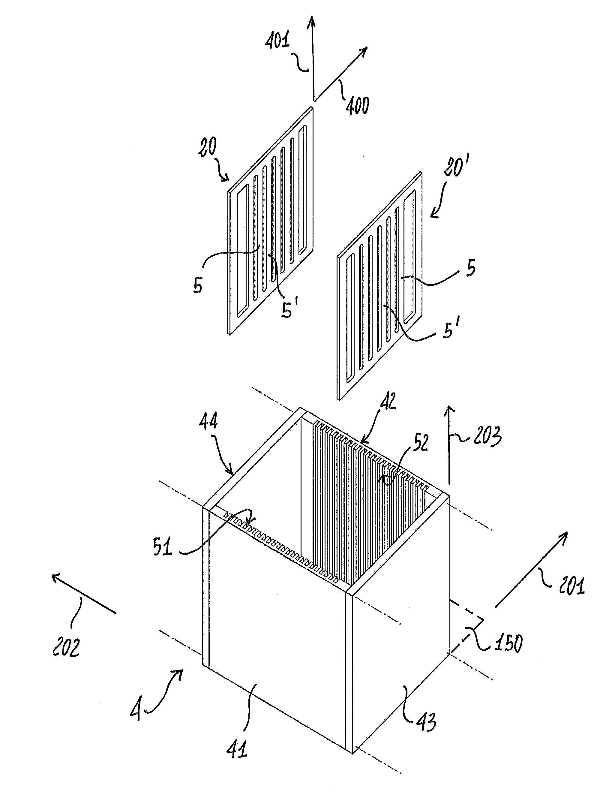
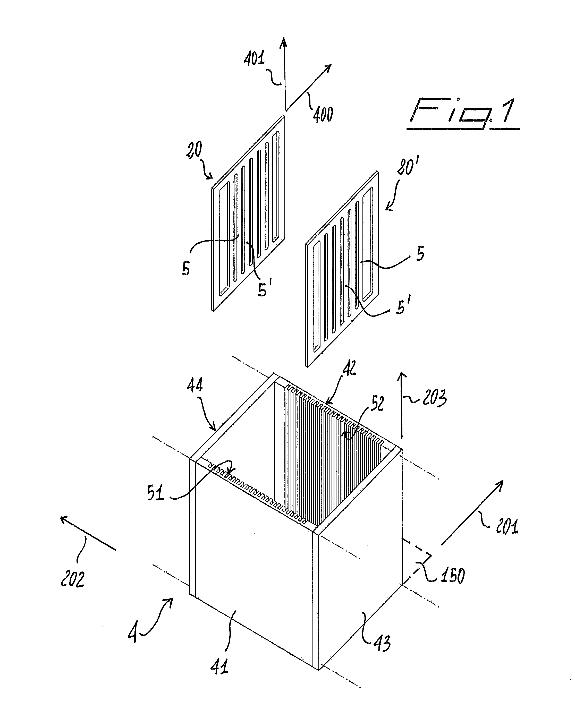
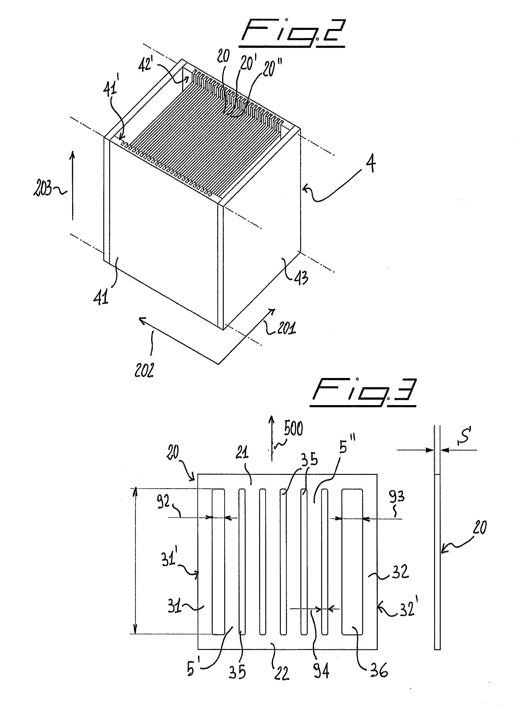
The present invention relates to a method for manufacturing prism-shaped panels (1), each comprising through portions (55) made of translucent material adapted to transmit light between two opposite sides of the panel. The method includes arranging a plurality of elements (5, 5′, 5″) made of translucent material in a formwork so that the main direction of development (500) of such elements is parallel to the vertical direction of development (203) of the formwork. The method includes pouring cementitious mortar into said formwork (4) so that said cementitious mortar is distributed between said elements and so as to generate, after the hardening of said cementitious mortar, a substantially prism-shaped semi-finished cementitious mortar product (2) in which said elements made of translucent material are incorporated. The method further includes extracting the semi-finished product from said formwork after the hardening of the cementitious mortar, and cutting the semi-finished product according to cutting planes orthogonal to the longitudinal direction (500) in which the elements incorporated in said semi-finished product develop, so as to obtain prism-shaped parts, each of which corresponds to one of said panels (1).

Description

FIELD OF THE INVENTION[0001]The present invention relates to the production of cementitious mortar products with properties of transparency to the light. In particular, the present invention relates to a method for manufacturing prism-shaped panels comprising a plurality of translucent portions passing through the panel to transmit light between two opposite sides of the panel.BACKGROUND ART[0002]In the field of constructions is known the use of cementitious mortar products with properties of transparency to light. According to a first known embodiment (described, for example, in patent application WO03097954), such cementitious mortar products are made in the form of cementitious mortar blocks internally crossed by optical fibers which permit the transmission of light from one side to the other of the block itself. In particular, the optical fibers are located as a warp in meshes or special fabrics, and are thus inserted in cementitious mortar poured into formworks to provide block...

Claims


Application Information

Patent Timeline
Patent Type & Authority Applications(United States)
IPC IPC(8): B29C39/10E04C2/04
CPCB29C39/10B29L2007/002B29K2033/12E04C2/044B28B23/0037B28B1/14B28B11/14B28B23/0056E04C2/54
Inventor CANGIANO, STEFANOCARMINATI, ARONNE
Owner ITALCEMENTI
Learn More