Method and system for engine cooling system control

a technology of engine cooling system and cooling system, applied in the direction of machines/engines, liquid/fluent solid measurement, instruments, etc., can solve the problems of poor cooling performance, inability to realize similar losses in cooling system performance, and large air volume to build sufficient pressure, so as to increase the number of reliable data points, improve the accuracy and reliability of determining the coolant level of the coolant overflow reservoir, and avoid the effect of inability to accurately estimate the coolant level

Active Publication Date: 2016-06-30
FORD GLOBAL TECH LLC
View PDF6 Cites 25 Cited by
  • Summary
  • Abstract
  • Description
  • Claims
  • Application Information

AI Technical Summary

Benefits of technology

[0007]In this way, an accuracy and reliability of determining a coolant level of a coolant overflow reservoir can be increased. By inferring the coolant level of the reservoir based on an estimated coolant level of a standpipe coupled to the reservoir, inaccuracies in coolant level estimation due to distortion of an in-tank sensor output during thermal fluctuations, or vehicle motion, is reduced. By enabling each of echo time raw data and processed data to be available for coolant level estimation, a controller m...

Problems solved by technology

If the coolant level in bottle is too low, the air volume will be too large to build sufficient pressure to prevent boiling and cavitation at the water pump inlet.
At low fluid levels, the degas bottle will also no longer be able to separate air from the coolant and air can be drawn into the cooling system, again leading to poor cooling performance.
If an overflow system is employed instead of an active degas system, a similar loss in cooling system performance can be realized when fluid levels are low.
As a result, there may be inconsistencies in the estimated coolant level.
Additionally, du...

Method used


Image

  • Method and system for engine cooling system control
  • Method and system for engine cooling system control
  • Method and system for engine cooling system control

Examples


Embodiment Construction

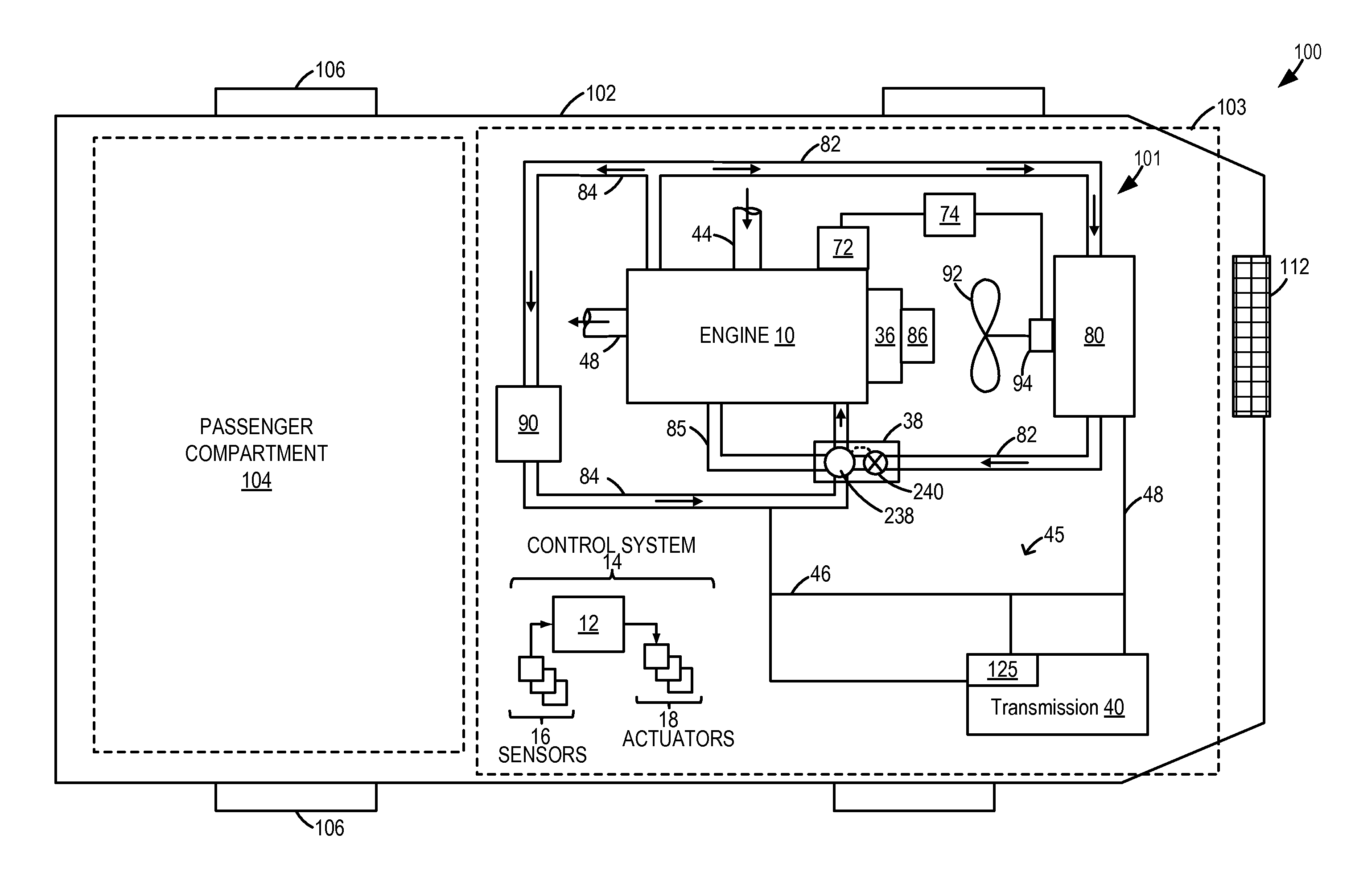
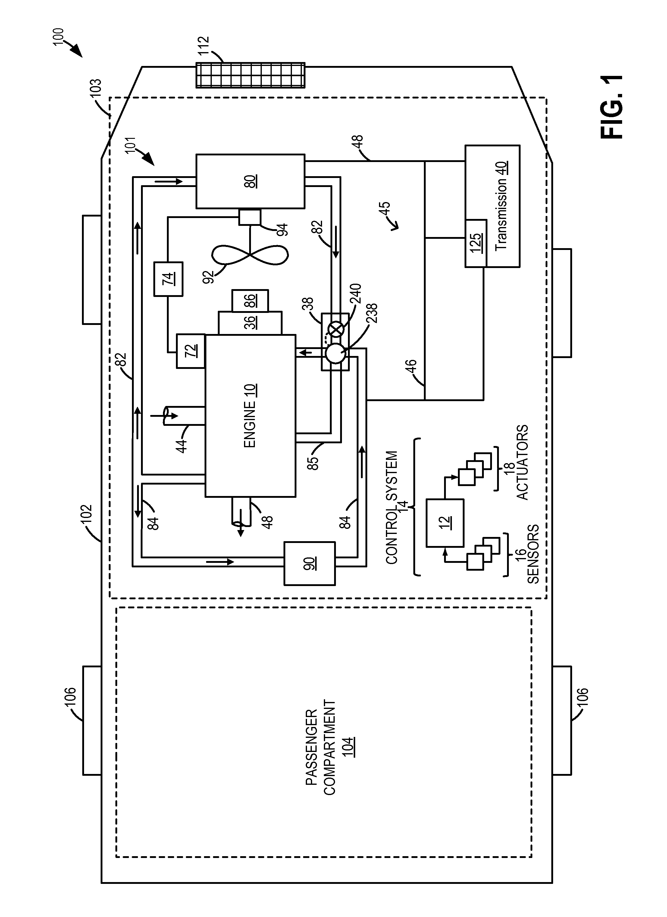
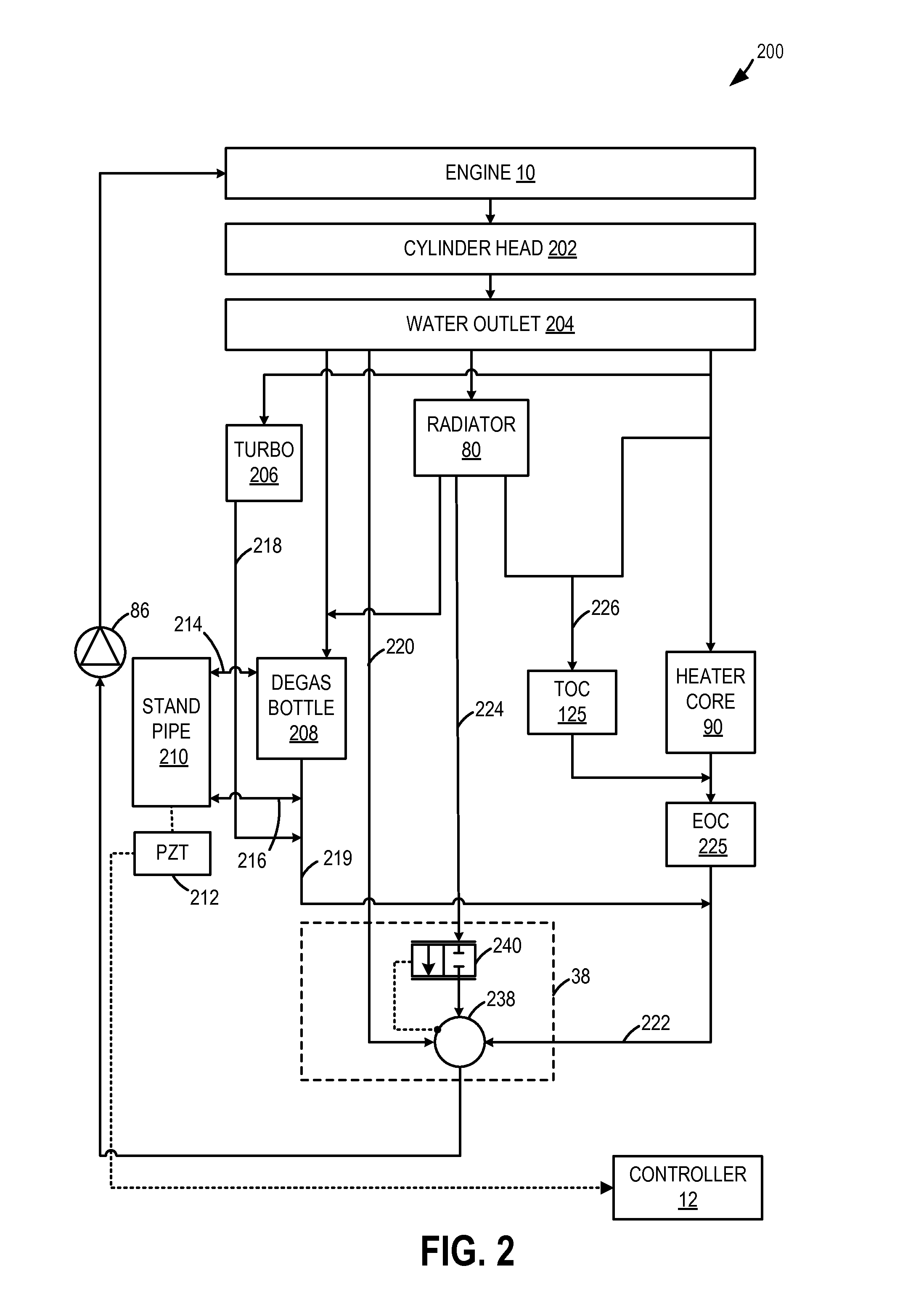
[0028]The following description relates to systems and methods for controlling an engine of a vehicle, the engine having a cooling system such as that of FIGS. 1-2. The cooling system may include a coolant overflow reservoir, herein also referred to as a degas bottle, fluidly connected to a narrow vertical standpipe, as discussed at FIGS. 3-8. The vertical standpipe may include a level sensor broadcasting information to an engine controller for determining an amount of coolant within the standpipe, as elaborated at FIGS. 9-12. The controller may also estimate an amount of coolant within the degas bottle (herein also referred to as a bulk coolant level), based on the amount of coolant within the standpipe (herein also referred to as a local coolant level) and various motion parameters, as described at FIGS. 13-17. Based on the estimate of coolant, the controller may indicate a coolant state, and based on the coolant state, restrictions may be placed on engine operating parameters, as...


PUM


Abstract

Methods and systems are providing for improving engine coolant level estimation to reduce engine overheating. The level of fluid in a coolant overflow reservoir is inferred based on the fluid level in a hollow vertical standpipe fluidically coupled to the reservoir at top and bottom locations, while the fluid level in the standpipe is estimated based on output from an ultrasonic signal transmitted by a sensor positioned in a recess at the bottom of the vertical standpipe. The sensor uses a combination of raw echo times and processed fluid level data to estimate the fluid level accurately and reliably.

Description

FIELD[0001]The present application relates to methods and systems for inferring a fluid level in a coolant overflow container (or degas bottle), and adjusting engine operation, based on a fluid level estimated in a vertical hollow standpipe fluidically coupled to the overflow container.BACKGROUND AND SUMMARY[0002]Vehicles may include cooling systems configured to reduce overheating of an engine by transferring the heat to ambient air. Therein, coolant is circulated through the engine block to remove heat from the engine, the heated coolant then circulated through a radiator to dissipate the heat. The cooling system may include various components such as a coolant reservoir coupled to the system for degassing and storing coolant. A pressurized reservoir that also serves to separate entrained air from the coolant is typically called a degas bottle. When the temperature of coolant anywhere in the system rises, thermal expansion of the coolant causes pressure to rise in the degas bottle...

Claims


Application Information

Patent Timeline
IPC IPC(8): F01P11/18F02D35/00G01F23/296F01P11/02
CPCF01P11/18G01F23/296F02D35/0007F01P11/02F01P11/028F01P2050/22F01P2025/70F01P11/14G01F23/2962
Inventor ROLLINGER, JOHN ERICJENTZ, ROBERT ROYGOODWIN, WILLIAM RUSSELLGRIFFIN, CHAD EVERETTEDIETRICH, CASEYGEROW, MATTTHOMPSON, SCOTT STEADMON
Owner FORD GLOBAL TECH LLC
Why Eureka
Try Eureka