Outboard motor

a technology for outboard motors and motors, applied in the field of outboard motors, can solve the problems of unexpected increase in fuel vapor amount, relatively high temperature of the surrounding crankcase, and increase in cost accordingly, so as to shorten the high-pressure fuel pipe, reduce the effect of high temperature and reduce the effect of leaking

Active Publication Date: 2016-06-30
SUZUKI MOTOR CORP
View PDF4 Cites 1 Cited by
  • Summary
  • Abstract
  • Description
  • Claims
  • Application Information

AI Technical Summary

Benefits of technology

[0023]According to the present invention, it is possible to arrange components around the vertical-shaft vee engine unit without being affected by heat. That is, since the electrical component is arranged in a lateral side of the air intake system unit, it is possible to obtain efficient wiring and improve cooling efficiency. In addition, since the fuel supply system component is arranged in a lateral side of the air intake system unit, it is possible to prevent the fuel supply system component from being affected by heat. When the fuel supply system component is the vapor separator, it is possible to shorten the high-pressure fuel pipe.

Problems solved by technology

However, since heat is emitted to the surroundings from the crankcase and the like, the surroundings of the crankcase have a relatively high temperature.
For this reason, if a vapor separator is arranged around the crankcase, the vapor separator is affected by the heat, and a temperature increases, so that a fuel vapor amount may increase unexpectedly.
Since the high-pressure fuel pipe is expensive more than the low-pressure fuel pipe, cost increases accordingly.

Method used


Image

  • Outboard motor
  • Outboard motor
  • Outboard motor

Examples


Embodiment Construction

[0035]A description will now be made for embodiments of the present invention with reference to the accompanying drawings.

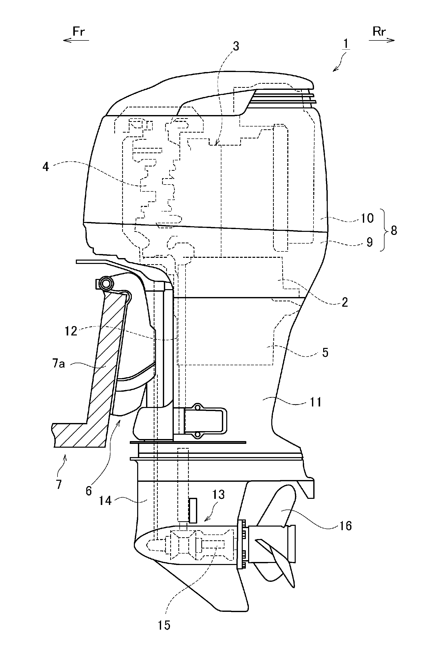
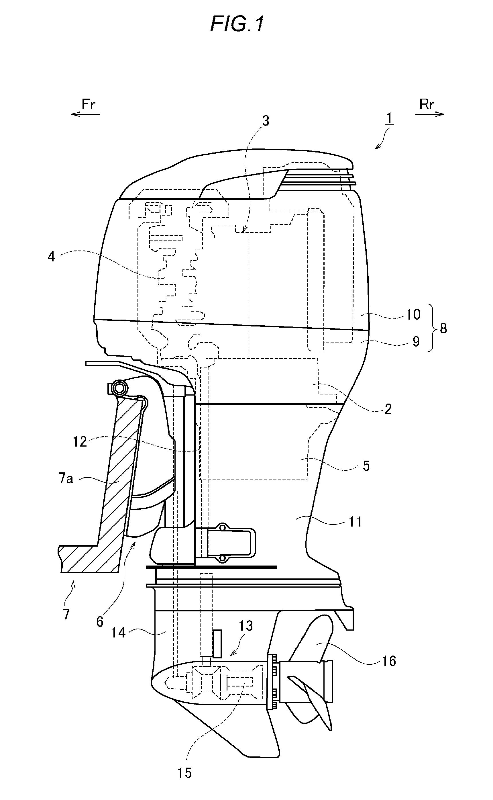
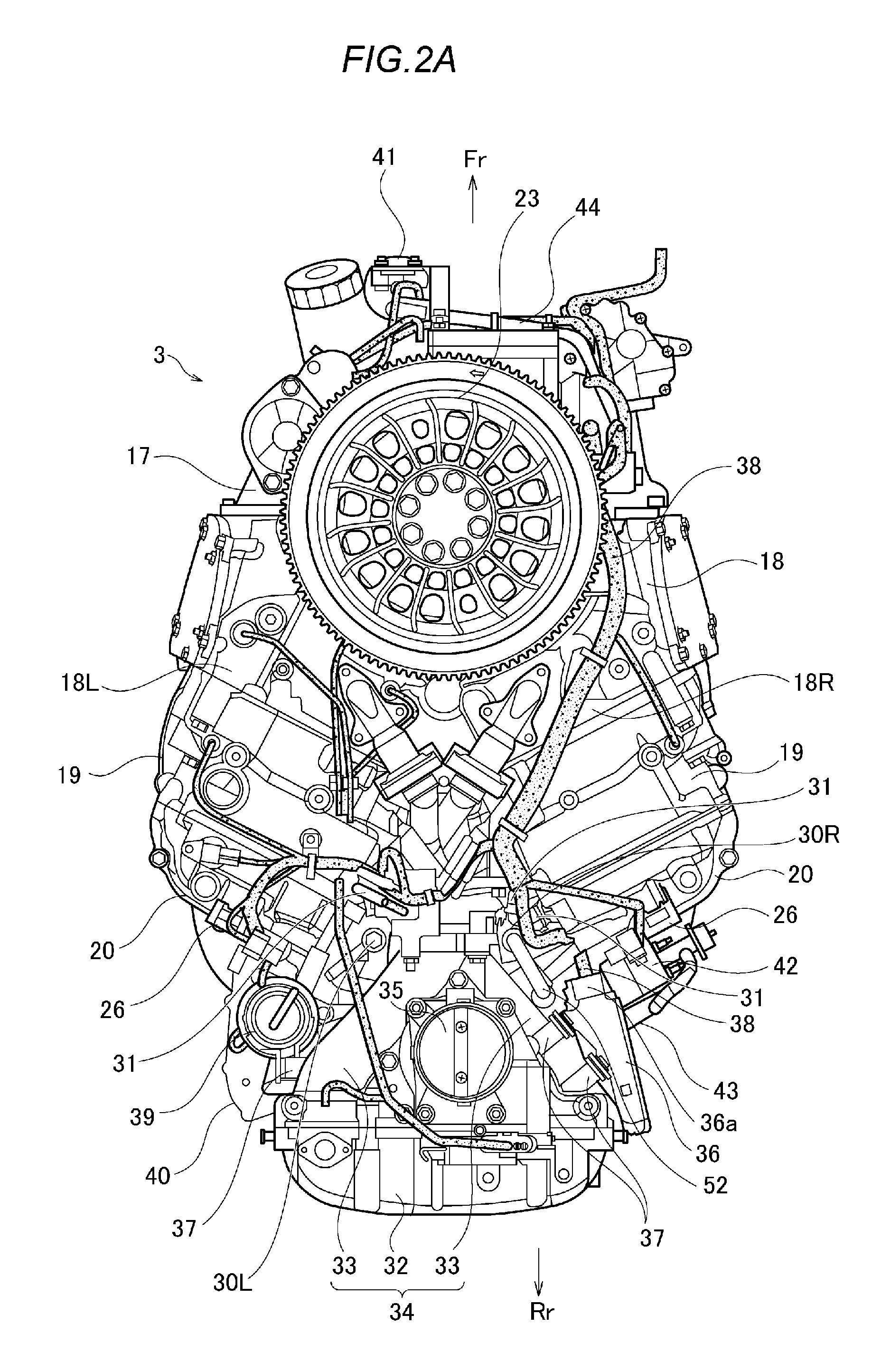
[0036]Referring to FIG. 1, an outboard motor 1 has an engine holder 2 and an engine unit 3 mounted on the engine holder 2. A crankshaft 4 is approximately vertically arranged inside the engine unit 3, and left and right cylinder units are aligned to be open backward in a “V” shape as seen in a plan view. That is, the outboard motor 1 has a vertical-shaft water-cooled four-cycle six-cylinder vee (V6) engine unit with V-banks (refer to FIGS. 2A and 2B).

[0037]Under the engine holder 2, an oil pan 5 for storing lubricating oil is disposed. A bracket device 6 is installed in the outboard motor 1, so that the outboard motor 1 is mounted to a transom 7a of a ship 7 by using this bracket device 6. Herein, each direction is defined by indicating the ship 7 side as a front direction. In each drawing, “Fr” denotes a front direction, and “Rr” denotes a rear direction.

[0038]T...


PUM


Abstract

An outboard motor has a vertical-shaft vee engine unit provided with a crankshaft arranged approximately vertically and left and right cylinder units aligned to be open backward in a “V” shape as seen in a plan view. A surge tank and an air intake system unit provided with an intake pipe to connect the surge tank to intake ports of the left and right cylinder heads are arranged in a center of a width direction of a rear side of the engine unit. In addition, an electronic control unit is arranged in an approximate center of a height direction in the right side of the air intake system unit. Furthermore, a high-pressure fuel filter is arranged in an approximate center of a height direction in the left side of the air intake system unit. Moreover, a vapor separator embedded with a high-pressure fuel pump is arranged under the high-pressure fuel filter.

Description

CROSS-REFERENCE TO RELATED APPLICATIONS[0001]This application is a continuation application of PCT International Application No. PCT / JP2015 / 062952, filed on Apr. 30, 2015 and designated the U.S., which claims the benefit of priority of the prior Japanese Patent Application Nos. 2014-113058, filed on May 30, 2014, and the prior Japanese Patent Application No. 2014-113061, filed on May 30, 2014, the entire contents of which are incorporated herein by reference.TECHNICAL FIELD[0002]The present invention relates to an outboard motor having a vertical-shaft vee internal combustion engine unit.BACKGROUND ART[0003]An outboard motor having an engine unit is provided with an electronic control unit for controlling the engine unit.[0004]As one of such types of technologies, there is known an engine control unit (ECU) arranged on a front face of a cylinder block of an engine body.[0005]Desirably, the electronic control unit is arranged around the engine unit, which is a control target, for eff...

Claims


Application Information

Patent Timeline
Patent Type & Authority Applications(United States)
IPC IPC(8): F02D41/00F02M37/04F02M25/08F02M37/22B63H20/00F02M35/10F02M37/32
CPCF02D41/003B63H20/00F02M35/10222F02M37/04F02M25/0872F02M37/22F02M25/0854F02M37/20F02B61/045F02D2011/102F02D2400/18F02D2400/21B63H20/32F02M35/10242F02M35/10249F02M35/116F02M35/167F02M37/32F02M35/16
Inventor ACHIWA, TETSUSHIDAIKOKU, KEISUKE
Owner SUZUKI MOTOR CORP
Why Eureka
Try Eureka