
Sequential and Coordinated Flashing of Electronic Roadside Flares With Active Energy Conservation

a technology energy conservation, applied in the field of electronic roadside flares, can solve the problems of lack of sequenced lights, poor visibility, and arrows not guiding the driver, and achieve the effect of facilitating the use of separate groups of flares

Active Publication Date: 2016-06-30
SELEVAN JAMES R +1
View PDF10 Cites 21 Cited by
  • Summary
  • Abstract
  • Description
  • Claims
  • Application Information

AI Technical Summary

Benefits of technology

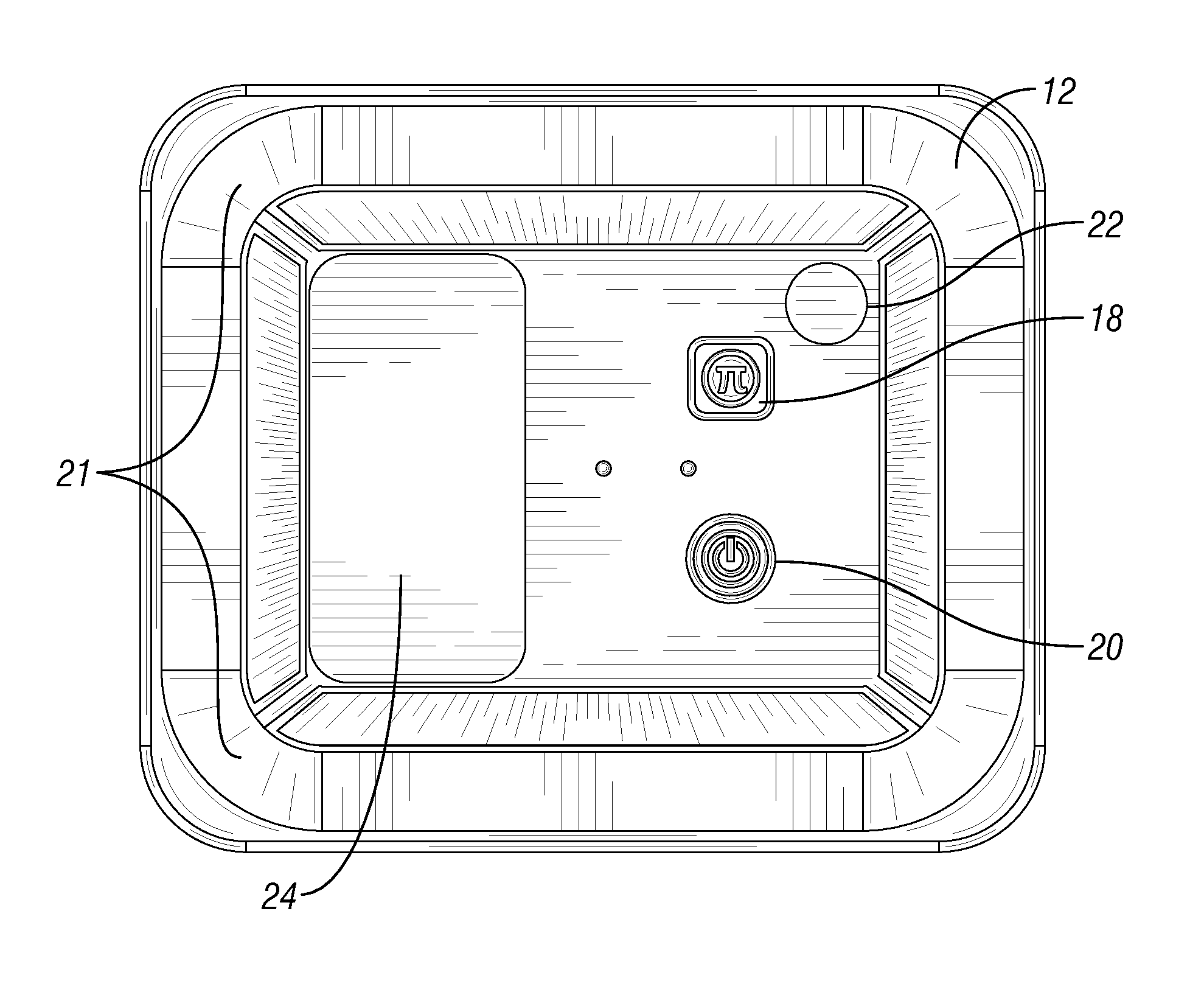
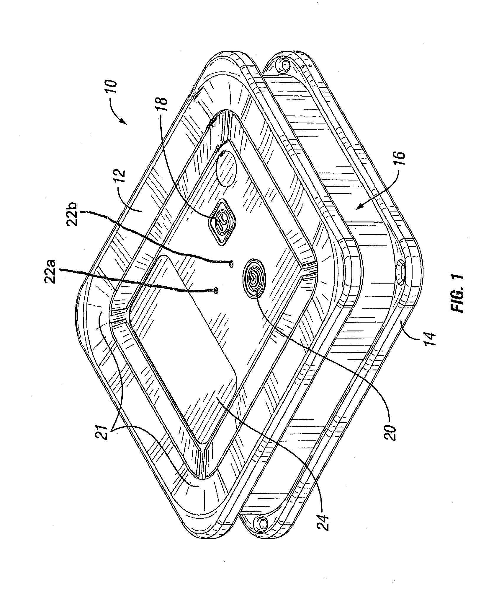
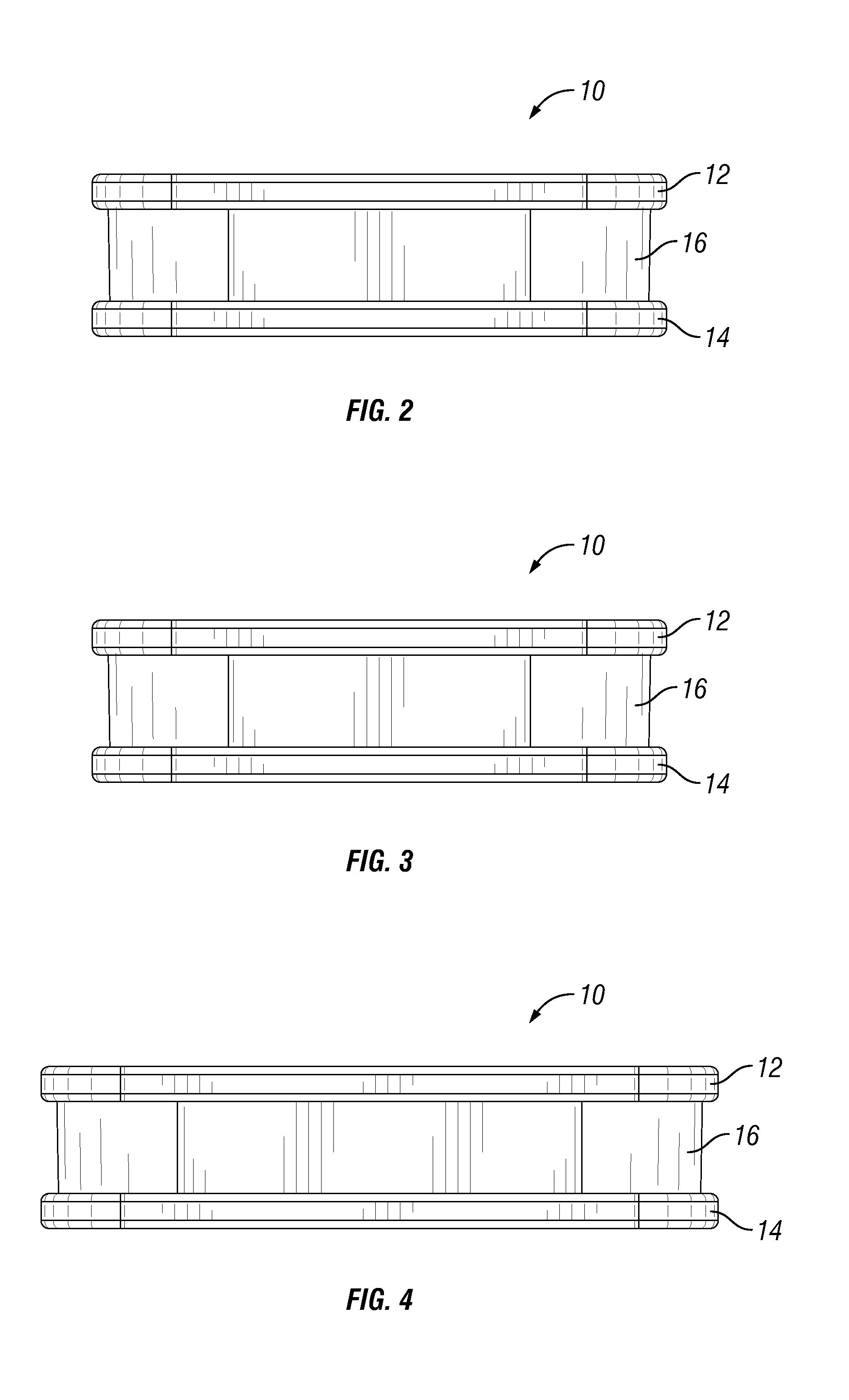
The present invention provides new electronic flare devices and their methods of use. These flare devices have a housing with a translucent side wall and a plurality of light emitters. They can be used for various features such as self-synchronization, remote control, motion-actuated or percussion-actuated features, dynamic shifting between side-emitting and top-emitting light emitters, overrides to cause continued emission from side-emitting or top-emitting light emitters irrespective of changes in the flare's positional orientation, and many more. The flare devices can also be used for illumination of traffic cones and other hazard marking or traffic safety objects or devices, and there are group on / off features, frequency specificity to facilitate use of separate groups of flares in proximity to one another, and many more.

Problems solved by technology

These passive cones are typically used over an entire 24-hour period, which includes darkness and may include poor visibility.
These signs create a large arrow that directs traffic, but the arrow does not guide the driver around a curve or through unfamiliar road courses.
Similarly, nautical traffic entering a harbor is guided via buoys and shore-based lights, which when set upon the backdrop of terrestrial lighting, can be confusing.
Similarly, emergency or temporary aircraft runways for military, civilian, police, and Coast Guard air equipment, both fixed wing and rotary wing, lack proper sequenced lights that designate direction and location of the runway.
There has been movement away from use of flame flares as they result in fire danger, pollution, and toxic fumes.
This “light noise” can introduce confusion to an approaching driver.

Method used


Image

  • Sequential and Coordinated Flashing of Electronic Roadside Flares With Active Energy Conservation
  • Sequential and Coordinated Flashing of Electronic Roadside Flares With Active Energy Conservation
  • Sequential and Coordinated Flashing of Electronic Roadside Flares With Active Energy Conservation

Examples


Embodiment Construction

[0022]The following detailed description and the accompanying drawings to which it refers are intended to describe some, but not necessarily all, examples or embodiments of the invention. The described embodiments are to be considered in all respects only as illustrative and not restrictive. The contents of this detailed description and the accompanying drawings do not limit the scope of the invention in any way.

[0023]The ability to coordinate the pattern of illumination between electronic roadside flares enhances the approaching driver's perspective. Sequential flashing provides directional information, while simultaneous flashing provides a more dramatic “warning”. One method of coordinating flash timing of roadside flares is to connect them via a single wire. However, this method does introduce the entanglement of the wire in the storage container, the potential for workers to trip over the wire, and delayed deployment.

[0024]Wireless coordination of flashing between flares (e.g.,...


PUM


Abstract

Electronic light emitting flares and related methods. Flares of the present invention include various features such as self-synchronization, remote control, motion-actuated or percussion-actuated features, dynamic shifting between side-emitting and top-emitting light emitters in response to changes in positional orientation (e.g., vertical vs. horizontal) of the flare; overrides to cause continued emission from side-emitting or top-emitting light emitters irrespective of changes in the flare's positional orientation; use of the flare(s) for illumination of traffic cones and other hazard marking or traffic safety objects or devices, group on / off features, frequency specificity to facilitate use of separate groups of flares in proximity to one another, selection and changing of flashing patterns and others.

Description

RELATED APPLICATIONS[0001]This patent application claims priority to copending U.S. Provisional Patent Application No. 62 / 080,294 filed Nov. 15, 2014 and this patent application is also a continuation in part of U.S. Design patent application Ser. No. 29 / 525,453 filed Apr. 29, 2015, the entire disclosure of each such prior application being expressly incorporated herein by reference.FIELD OF THE INVENTION[0002]The present invention relates generally to the fields of electronics and traffic engineering and more particularly to flare devices and methods for marking hazards or intended routes of travel on roadways and the like.BACKGROUND OF THE INVENTION[0003]Pursuant to 37 CFR 1.71(e), this patent document contains material which is subject to copyright protection and the owner of this patent document reserves all copyright rights whatsoever.[0004]Flashing orange traffic safety lamps are commonplace along highways and waterways. Passive cones are often used to mark the boundaries or e...

Claims


Application Information

Patent Timeline
Patent Type & Authority Applications(United States)
IPC IPC(8): F21V23/04H05B37/02F21L4/02F21V23/00H05B33/08F21V33/00H05B44/00
CPCF21V23/0407H05B33/0845F21V33/0076F21L4/02F21Y2101/02F21V23/0471H05B37/0272F21W2111/02F21V23/003G08G1/0955G08B5/006F21Y2115/10F21L2/00H05B47/155H05B47/105H05B47/19H05B45/12H05B47/195H05B45/10
Inventor SELEVAN, JAMES R.SELEVAN, DANIEL
Owner SELEVAN JAMES R
Learn More