Cooling system and method for a magnetic resonance imaging device

a cooling system and magnetic resonance imaging technology, applied in the field of magnetic resonance imaging, can solve the problems of inability to cool down, and inability to produce sufficient heat,

Inactive Publication Date: 2016-06-30
GE PRECISION HEALTHCARE LLC
View PDF5 Cites 10 Cited by
  • Summary
  • Abstract
  • Description
  • Claims
  • Application Information

AI Technical Summary

Problems solved by technology

However, during ramp, considerable heat may be generated, mainly in leads, switches and heaters, which is transferred to and deposited in the cold mass assembly.
The heat coming to the cold mass that contains the coils may lead to boil-off or evaporation of the cryogen, requiring replenishment.
However, from time to time the cooling may be interrupted in the MRI devices located in clinical environment.
Another condition when cooling power ceases to be provided to the superconducting magnet is a power outage.
During the outage, the non-operating coldhead introduces thermal short that may input additional heat to the superconducting system.
Indeed, for magnets with closed helium inventory, i.e., low cryogen type magnets, the duration of tolerable power outage, coldhead service or ramp profile is limited by the volume of accumulated liquid helium that boils off or evaporates during the above conditions with extra heat load.

Method used


Image

  • Cooling system and method for a magnetic resonance imaging device
  • Cooling system and method for a magnetic resonance imaging device
  • Cooling system and method for a magnetic resonance imaging device

Examples


Embodiment Construction

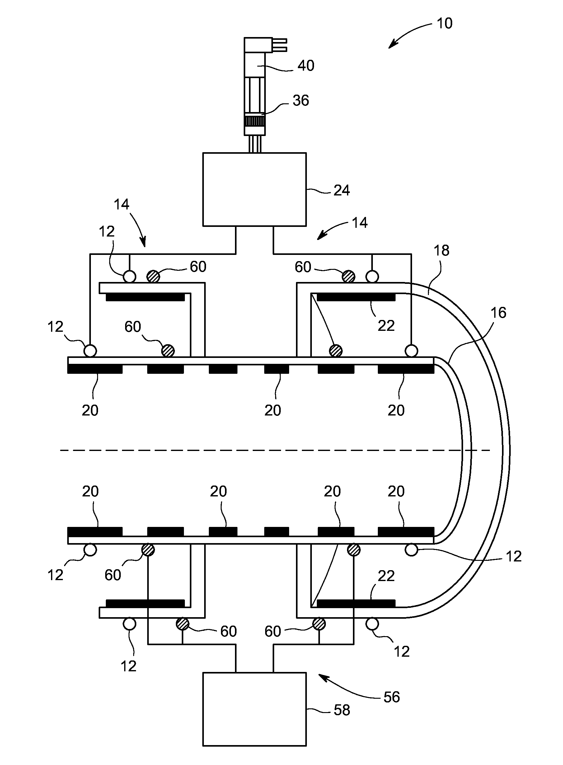
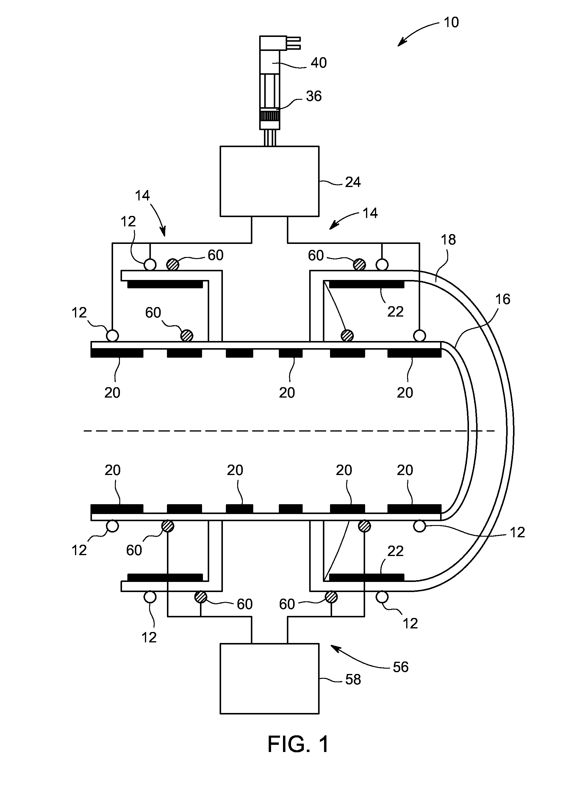
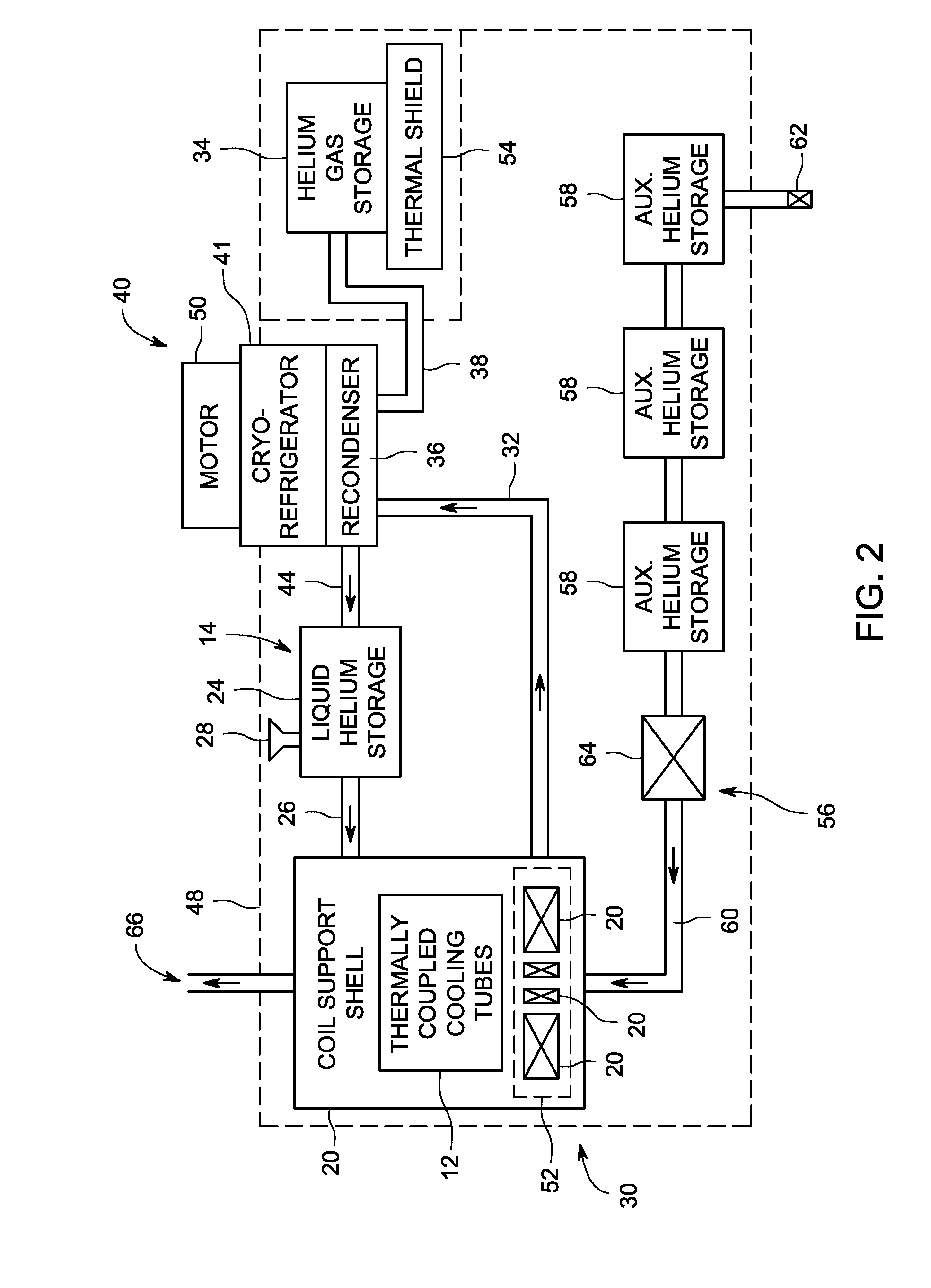
[0020]Reference will be made below in detail to exemplary embodiments of the invention, examples of which are illustrated in the accompanying drawings. Wherever possible, the same reference characters used throughout the drawings refer to the same or like parts. Although embodiments of the present invention are described as intended for use with superconducting magnets embodied in MRI machines, the present invention may also be used for the cooling of superconducting magnets, generally, irrespective of their specific end use. The superconducting magnets may also be implemented in other types of medical imaging devices, as well as non-medical imaging devices.

[0021]As used herein, “thermally coupled,”“thermally connected” and “thermal communication” means that two physical systems or components are associated in such a manner that thermal energy and heat may be transferred between such systems or components. For example, such thermal communication can be achieved, without loss of gene...


PUM


Abstract

A cooling system includes a first cooling loop having a first cooling fluid configured for circulation therethrough and a second cooling loop having a second cooling fluid configured for circulation therethrough. The first cooling loop is in thermal communication with the superconducting magnet and is configured to provide primary cooling for the magnet, and the second cooling loop is in thermal communication with the superconducting magnet and is configured to provide secondary cooling for the magnet.

Description

BACKGROUND[0001]1. Technical Field[0002]Embodiments of the invention relate generally to magnetic resonance imaging and, more specifically, to a cooling system and method for a magnetic resonance imaging device.[0003]2. Discussion of Art[0004]Magnetic resonance imaging (MRI) machines work by generating a very strong magnetic field using a superconducting magnet which consists of many coils or windings of wires through which a current is passed. Creating a strong magnetic field is accomplished using superconductivity, which involves reducing the resistance in the current-carrying conductors to practically zero by cooling them to ultra-low temperatures below the superconducting limits This may be achieved by immersing the coils in a bath of liquid cryogen, such as liquid helium, and / or by circulating liquid cryogen within cooling loops adjacent to, or through, the coils, or by providing solid conductive pathways that allow to withdraw heat from the coils.[0005]As will be readily appre...

Claims


Application Information

Patent Timeline
Patent Type & Authority Applications(United States)
IPC IPC(8): G01R33/34
CPCG01R33/34023G01R33/3403G01R33/3804G01R33/3815H01F6/04
Inventor JIANG, LONGZHILVOVSKY, YURIFELTHAM, STUART PAUL
Owner GE PRECISION HEALTHCARE LLC
Why Eureka
Try Eureka