
Superconducting cable

a superconducting cable and cable technology, applied in the direction of superconducting magnets/coils, cables, insulated conductors, etc., can solve the problems of cable current-carrying properties degradation, high ac loss, and decrease of yield

Inactive Publication Date: 2006-08-15
SUMITOMO ELECTRIC IND LTD
View PDF11 Cites 5 Cited by
  • Summary
  • Abstract
  • Description
  • Claims
  • Application Information

AI Technical Summary

Benefits of technology

[0010]Accordingly, it is an object of the present invention to provide a superconducting cable in which the AC loss can effectively be reduced without causing the degradation of the current-carrying properties and the increase of cost.

Problems solved by technology

Such nonuniform current flow causes each layer to behave electromagnetically as a single block (i.e., so-called mono-block model), which results in high AC loss.
In such case, however, there are problems in that the application of twisting in the process of forming superconducting wires causes a reduction of critical current (Ic) and breakage of filament wires, etc., resulting in the decrease of the yield, the degradation of current-carrying properties of the cable, and the increase of manufacturing cost.

Method used


Image

  • Superconducting cable
  • Superconducting cable
  • Superconducting cable

Examples


example 1

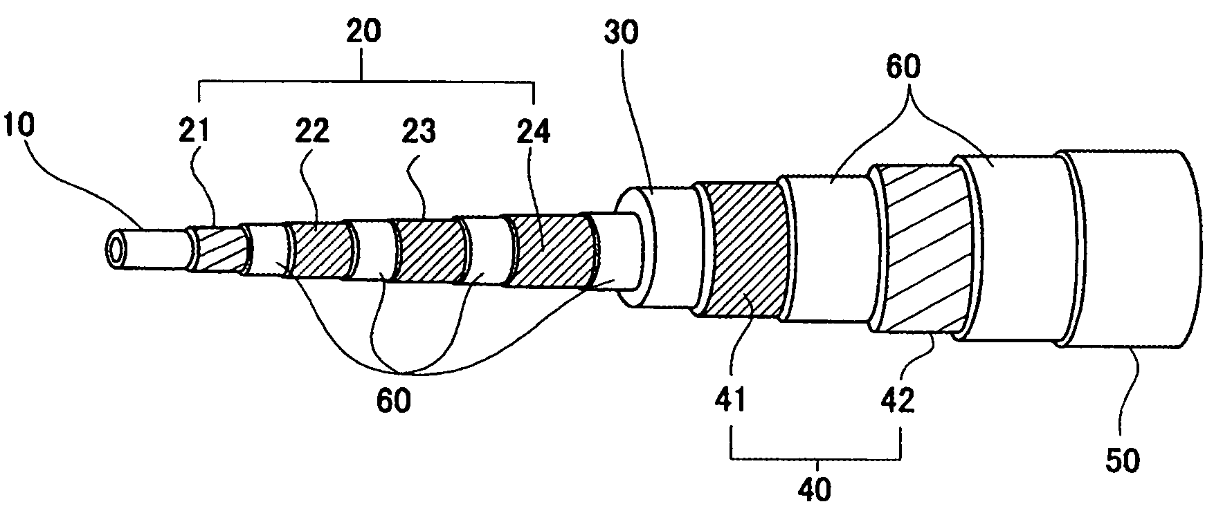
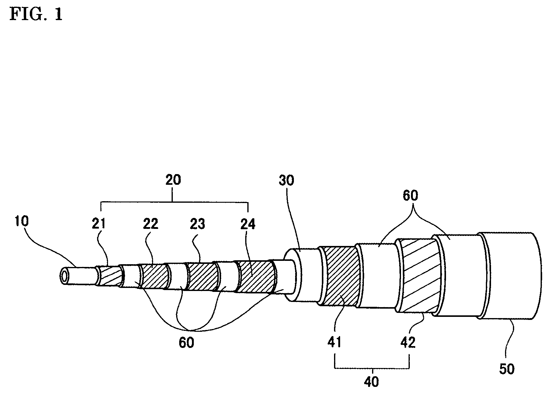
[0058]A cable conductor having the structure shown in FIG. 1 was fabricated using the above-described sample wires. The specifications of the fabricated cable (Example 1) are shown in Table II. The cable has a stranded-wire former formed of stranded insulated Cu wires, a four-layer conductor layer over the former, and an insulation layer (with a thickness of 7 mm), and a two-layer magnetic shielding layer. The winding pitches and winding directions of the superconducting wires forming the conductor layer and the magnetic shielding layer were adjusted so as to exhibit a uniform current-carrying property.

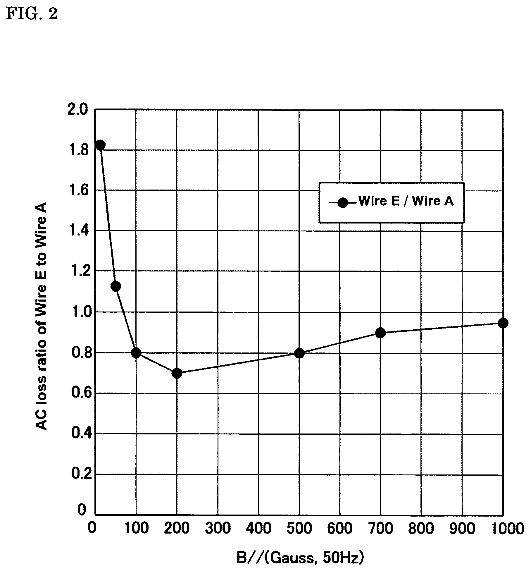
[0059]A layer in which the maximum applied magnetic field was less than 100 Gauss was formed using the untwisted filament type superconducting wire A, and a layer in which the maximum applied magnetic field was 100 Gauss or higher was formed using the twisted filament type superconducting wire E. Specifically, the second, third, and fourth layers of the conductor layer and the first l...


PUM

PropertyMeasurementUnit
Lengthaaaaaaaaaa
Lengthaaaaaaaaaa
Temperatureaaaaaaaaaa

Abstract

A superconducting cable has a plurality of superconducting wires wound around a core material (former) in a multilayered manner. The superconducting wires employ a twisted filament type superconducting wire having spiral superconducting filaments and an untwisted filament type superconducting wire having straight superconducting filaments. The layer in which an applied magnetic field is large and of which the low loss effect is expected is formed of twisted filament type superconducting wires, and the other layers are formed using the untwisted filament type superconducting wires; thus the AC loss can be reduced effectively. Thus, in the superconducting cable, the AC loss can be effectively reduced while a degradation of the current characteristics and the increase of cost are suppressed.

Description

BACKGROUND OF THE INVENTION[0001]1. Field of the Invention[0002]The present invention relates to superconducting cables, and particularly to a multilayer high-temperature superconducting cable in which alternating current (AC) loss can be reduced.[0003]2. Description of the Related Art[0004]Advances have been made in the development of compact, bulk-power-transmission superconducting cables. Superconducting cables generally have a multilayer cable structure in which a plurality of layers of superconducting tapes are spirally wound around a core material (former). Superconducting tapes are Bi-based Ag-sheathed superconducting tapes having Bi-based high-temperature superconducting filaments embedded in an Ag matrix, or the like.[0005]In such a multilayer cable structure, for example, when the tapes are wound with a constant pitch in winding directions which are alternately opposite with respect to adjacent layers, a nonuniform current flow occurs due to the difference in impedance amo...

Claims


Application Information

Patent Timeline
IPC IPC(8): H01B12/00H01B12/06H01B1/02H01B7/30H01B12/08H01B12/10H01B13/00
CPCH01B12/06H01B7/30Y10T29/49014Y02E40/642Y02E40/60
Inventor YUMURA, HIROYASUAYAI, NAOKI
Owner SUMITOMO ELECTRIC IND LTD
Learn More